High frequency communication (HF communication) is a type of communication in electrical networks that involves the use of high-voltage power lines as communication channels. The power lines of the electrical networks are leaking alternating current frequency 50 Hz. The essence of organizing HF communications is that the same wires are used to transmit a signal along the line, but at a different frequency.
The frequency range of HF communication channels is from tens to hundreds of kHz. High-frequency communication is organized between two adjacent substations, which are connected by a power line with a voltage of 35 kV and higher. In order to get to the buses of the substation switchgear, and communication signals to the corresponding communication sets, high-frequency suppressors and communication capacitors are used.
The RF suppressor has a small resistance at power frequency current and a high resistance at the frequency of high-frequency communication channels. coupling capacitor- on the contrary: it has high resistance at a frequency of 50 Hz, and at the frequency of the communication channel it has low resistance. Thus, it is ensured that only current with a frequency of 50 Hz reaches the substation buses, and only high-frequency signals reach the HF communication set.
To receive and process HF communication signals, special filters, signal transceivers and sets of equipment that perform certain functions are installed at both substations between which HF communication is organized. Below we will consider which functions can be implemented using HF communications.
Most important function– use of the HF channel in relay protection devices and automation of substation equipment. The HF communication channel is used in the protection of 110 and 220 kV lines - differential-phase protection and directional high-frequency protection. At both ends of the power line, protection kits are installed, which communicate with each other via an HF communication channel. Due to reliability, speed and selectivity, protection using an HF communication channel is used as the main one for each 110-220 kV overhead line.
There are also devices that, using an RF communication channel, determine the location of damage to power lines. In addition, the RF communication channel can be used to transmit signals, SCADA, automatic control systems and other automated process control equipment systems. Thus, via a high-frequency communication channel it is possible to control the operating mode of substation equipment, as well as transmit control commands for switches and various functions.
Another function - telephone function. The HF channel can be used for operational negotiations between adjacent substations. IN modern conditions this function is not relevant, since there are more convenient ways of communication between facility maintenance personnel, but the HF channel can serve as a backup communication channel in case of an emergency emergency when there is no mobile or landline telephone connection.
HF channels can be used to communicate with operational teams that repair sections of damaged power lines and eliminate damage to electrical installations. For this purpose, special portable transceivers are used.
To transfer information between protections and automation at the ends high voltage line a channel created for high-frequency currents using a phase-to-ground connection scheme is used.
The path includes one phase of the operating overhead line, which is connected to the ground through coupling capacitors at substations to create a closed loop for HF currents.
Most often, two remote phases “A” and “C” are used on the line to transmit commands at frequency No. 1 through one of them from the substation, and through the second to receive commands at frequency No. 2.
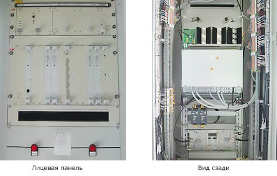
Design and purpose of the HF communication channel. Transmitters and receivers of high-frequency signals are installed at each substation. IN in this case Modern equipment of HF transceivers is made on the microprocessor base of ETL640 v.03.32 terminals from ABB.
To process signals at each frequency, its own transceiver is manufactured. Therefore, one substation requires 2 sets of terminals configured to simultaneously receive and transmit signals along different phases of the overhead line.
The connection of the HF transceiver to the overhead line is carried out by special equipment that separates high voltage from low-current equipment and creates a highway for transmitting HF signals. It is completed with:
High-voltage coupling capacitor (CC);
- connection filter (FP);
- high-frequency jammer (HF);
- HF cable.
The purpose of a high-voltage coupling capacitor is to reliably isolate from the ground power transported via overhead lines at industrial frequency and to pass high-frequency currents through it.
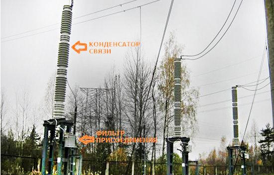
In the photograph of the line in question, there are 3 capacitors with PT in each phase. They are used to communicate with far-end equipment for the following purposes:
1. Transfer of commands to RZ and PA;
2. Receiving commands RZ and PA;
3. Work of HF equipment of the communication service.
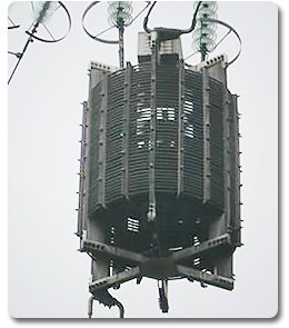 To separate the HF signal from the high-voltage equipment of the substation, an HF suppressor is mounted into the phase wire of the high-voltage overhead line. which limits the amount of RF signal loss through parallel circuits.
Industrial frequency currents pass through it well and high-frequency currents do not pass through. The VZ consists of a reactor (power coil) passing the operating current of the line, and adjustment elements connected in parallel with the reactor.
To match the parameters of the input impedances of the HF cable and line, a connection filter is used, which is performed as an air transformer model with taps from the windings, allowing the necessary adjustments to be made. The RF cable connects the connection filter to the transceiver.
High frequency transceivers (ETL640), purpose. Transceivers of the ETL640 type (PRM/PRD) are designed to transmit and receive HF signals in the form of commands generated by relay protection (RP) and emergency automatics (EA) to the opposite end of the overhead line.
Checking the serviceability of the HF channel. Complex RF transmission path equipment is located at distances of hundreds of kilometers and requires monitoring and maintaining its integrity. ETL640 transceivers at the ends of overhead lines constantly exchange (transmit/receive) control frequency signals during normal operation.
When the signal decreases in magnitude or its frequency changes beyond permissible limits, a fault alarm is triggered. After restoration of functionality, the transceiver automatically returns to normal operation.
Signal exchange. Signals are transmitted and received at dedicated frequencies, for example:
Complex on phase “A”: Tx: 470 + 4 kHz, Rx: 474 + 4 kHz;
- complex on phase “C”: Tx: 502 + 4 kHz, Rx: 506 + 4 kHz.
The ETL640 equipment is designed for round-the-clock continuous operation in heated control rooms.
Reception and transmission of commands. Terminals No. 1 and No. 2 of the ETL640 complexes receive and transmit 16 commands each from the RZ and PA.
ETL640 transceiver commands. Typical commands of the transceiver of any ETL640 complex can look like:
 1. Disconnection of 3 phases of the 330 kV overhead line from the far end of the overhead line without control with the prohibition of TAPV and start-up from the breaker failure or ZNR complex No.... REL-670;
2. Disconnection of 3 phases of the 330 kV overhead line from the far end of the overhead line with control by measuring elements Z3 DZ and the 3rd stage of the NTZNP complex No.... REL670 protections without prohibiting TAPV and starting from the 3-phase shutdown factor of the complex No.... REL protections;
3. Teleacceleration of remote protection with an effect on one or 3-phase shutdown of a 330 kV overhead line from the far end of the overhead line, with control of the parameters of stage Z3 of the remote protection complex No.... of REL670 protection with OAPV/TAPV and starting from stage Z3 of the remote protection complex No.... of protection REL- 670;
4. Teleacceleration of NTZNP with an effect on one or 3-phase shutdown of a 330 kV overhead line from the far end of the overhead line with control of the parameters of stage Z3 of NTZNP complex No.... REL670 protections with OAPV/TAPV and starting from the measuring element of the 3rd stage of NTZNP complex No.... REL670 protections ;
5. Fixation of line disconnection from its side of the overhead line and action in the AFOL logic circuit of the complex No.... protection of relay protection and automation. Start from the output relay of the AFOL logic circuit of complex No.... protection of relay protection and automation when the line is disconnected on its side;
6. III stage OH, acting on start-up:
- 5th command AKAP prd 232 kHz VL No....;
- 2nd command AKPA prd 286 kHz overhead line No....;
- 4th team ANKA prd 342 kHz VL No....
7. Fixing the switching on of the line on its part and the action in the AFOL logic circuit of the complex No.... of the VL RPA protection with starting from the output relay of the AFOL logic circuit of the complex No.... of the VL-330 RZA protection when switched on from its side;
8. Start from the 1st stage of the SAPAH circuit... with start:
- 6th team ANKA prd 348 kHz VL No....;
- 4th command AKAP prd 122 kHz VL No....
9. 3rd stage of load shedding with action...
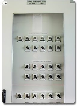
Each team is formed for specific conditions of the overhead line, taking into account its configuration in the electrical network and operating conditions. The output relays of the HF equipment and switching devices are located in a separate cabinet.
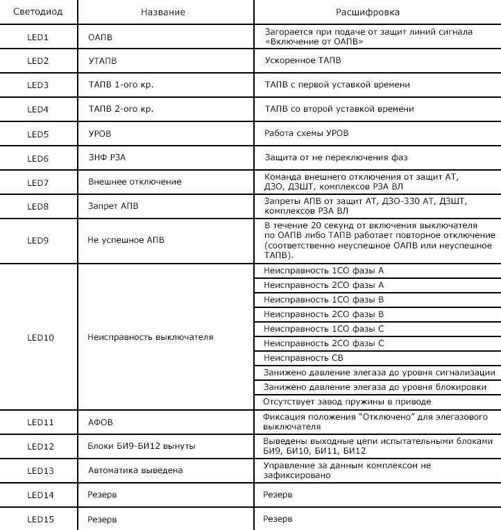
Overhead line alarm circuits. Terminal signaling. On the front panel of the terminals there are 3 LEDs that reflect the state of the REL670 device itself and 15 LEDs that indicate protection activations, malfunctions and the status of operational switches.
The LEDs of the terminals REL670 (protection of the 1st and 2nd complexes) and REC670 (automation and breaker failure of the 1st and 2nd complexes B1 and B2) of the first six numbers are red. LEDs numbered 7 to 15 are yellow.

LEDs for status indication. Above the LCD block of the REC670 and REL670 terminals there are 3 LED indicators “Ready”, “Start” and “Trip”. To indicate various information they glow different colors. Green color indicator means:
Device operation - stable glow;
- internal damage - flashing;
- lack of operative current supply - darkening of color.
The yellow indicator color indicates:
Starting the emergency recorder - steady glow;;
- the terminal is in test mode - accompanied by blinking.
The red color of the indicator indicates the issuance of an emergency shutdown command (stable light).
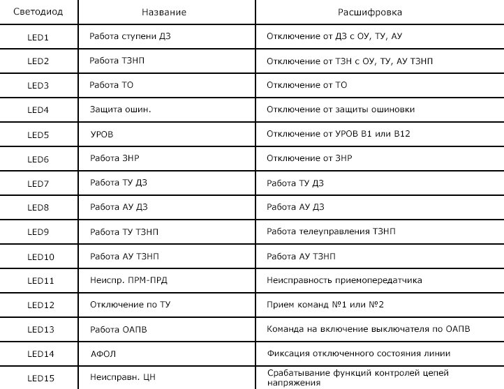
REC670 terminal LED signaling table
Resetting and testing the alarm. Resetting the alarm, counters for recording the reception and transmission of HF commands and information on the DZ and NTZNP zones for the terminal is done by pressing the SB1 button (alarm reset) on the front side of the cabinet.
To test the LEDs of the REL670 (REC670) terminals, you need to press and hold the SB1 button for more than 5 seconds.
Panel-wide light alarm. On the front side of the REС670 cabinets there are lamps:
- HLW – automatic reclosing works, ZNF, breaker failure;
- HLR2 – malfunction of automation systems and breaker failure level V-1 or V-2.
On the front side of REL670 cabinets there are lamps:
- HLW – protection work;
- HLR1 – the defense complex is removed;
- HLR2 – malfunction of protection systems.
On the front side of ETL cabinets there are alarm lamps:
- HLW1 – malfunction of ETL 1st complex;
- HLW2 – ETL 2nd complex malfunction.
Prospects for the development of overhead power line equipment. Time-tested air circuit breakers for high-voltage power lines are gradually being replaced by modern SF6 structures, which do not require Full time job powerful compressor stations to maintain air pressure in tanks and air lines.
Bulky analog relay protection and control devices for high-voltage equipment that require close attention service personnel, are replaced by new microprocessor terminals.
Page 16 of 21
The design of a power line, determined by its main purpose - transmission electrical energy over a distance, allows it to be used to transmit information. High level operation and high mechanical strength of the lines ensure the reliability of communication channels, close to the reliability of channels via cable lines communications. At the same time, when implementing communication channels over overhead lines for transmitting information, it is necessary to take into account the features of the lines that make it difficult to use them for communication purposes. Such a feature is, for example, the presence at the ends of the lines of substation equipment, which can be represented as a chain of varying within wide limits of series-connected reactive and active resistance. These resistances form a connection between overhead lines through substation buses, which leads to an increase in the communication path. Therefore, to reduce the influence between channels and attenuation, special barriers are used to block the paths of high-frequency currents towards substations.
Branches from overhead lines also significantly increase attenuation. These and other features of lines require the implementation of a number of measures to create conditions for information transfer.
The installation of HF channels along 6-10 kV distribution networks is associated with significant difficulties due to the specifics of constructing networks of these voltages. On sections of main lines 6-10 kV between adjacent switching points there is big number taps, lines are sectioned by disconnectors and switches, primary switching circuits of networks are often changed, including automatically, due to the greater damageability of lines of these voltages, their reliability is lower than B71 35 kV and higher. Signal transmission in distribution networks depends on many factors that influence signal attenuation: the length and number of taps, the material of the line wires, load, etc. The load can vary within wide limits. At the same time, disconnecting individual taps, as studies show, sometimes not only does not reduce attenuation, but, on the contrary, due to the violation of mutual compensation of attenuation between adjacent taps, increases it. Therefore, channels even of short length have significant attenuation and operate unstably. The operation of channels is also negatively affected by damage to insulators, poor-quality connections of wires and unsatisfactory condition of contacts of switching equipment. These defects are sources of interference commensurate with the level of the transmitted signal, which can cause termination of channel operation and damage to equipment. The presence of sectioning devices on the lines leads to a complete cessation of operation of the HF channel if they are disconnected and one of the line sections is grounded. The noted disadvantages significantly limit, although they do not exclude, the use of 6-10 kV lines for organizing HF channels. Still, it should be noted that widespread There is currently no HF communication via distribution networks.
According to their purpose, HF communication channels over power lines are divided into four groups: dispatch communication channels, technological, special and line-operational communication channels.
Without dwelling in detail on the use and purpose of each group of channels, we note that for control rooms and technological telephone communication channels, the voice frequency band of 300-3400 Hz is mainly used<300-2300). Верхняя часть тонального спектра (2400-3400 Гц) не пользуется для передачи сигналов телеинформации. Современная комбинированная аппаратура позволяет организовать в этом спектре до четырех независимых узкополосных каналов телеииформации.
Line-operational communication channels serve to organize communication between the dispatcher and repair crews working on the route of a long power transmission line or substations when there is no permanent connection with them. For these channels, simplified transportable and portable telephone equipment is used.
According to the degree of complexity, HF channels are divided into simple and complex. Channels consisting of only two sets of RF terminal equipment are called simple. Complex channels include intermediate amplifiers or several sets of terminal equipment (at the same frequencies).
Equipment of high-frequency communication channels via overhead lines.
The connection of communication equipment to the wires of a power line is carried out using special devices, the so-called line connection and processing equipment, consisting of a coupling capacitor, a barrier and protection elements.
Rice. 21. Scheme of a high-frequency communication channel via overhead lines
In Fig. Figure 21 shows a diagram of the formation of a communication channel via an overhead line. Signal transmission with high frequency currents is carried out by compaction equipment transmitters J, located at both ends of the overhead line at substations A and B.
Here, as part of the compaction equipment 1, there are receivers that receive modulated RF currents and convert them. To ensure the transmission of signal energy by HF currents through wires, it is enough to process one wire at each end of the line using a barrier 5, a coupling capacitor 4 and a connection filter 3, which is connected to the sealing equipment 1 using an HF cable 2. To ensure the safety of personnel working on the connection filter When the HF channel is operating, grounding knife 6 serves.
Connecting high-frequency equipment according to the diagram in Fig. 21 is called phase-earth. This scheme can be used to form single-channel and multi-channel information transmission systems. Other connection schemes are also used.
If it is necessary to connect equipment installed along the line route to a power transmission line (telephone mobile equipment of repair teams, equipment of a remotely controlled VHF radio station, etc.), antenna connection devices are usually used. Pieces of insulated wire of a certain length or sections of lightning protection cable are used as an antenna.
A high-frequency (linear) suppressor has a high resistance for the operating frequency of the channel and serves to block the path of these currents, reducing their leakage towards the substation. In the absence of a suppressor, the attenuation of the channel may increase, since the small input impedance of the substation shunts the RF channel. The barrier consists of a power coil (reactor), a setting element and a protection device. The power coil is the main element of the minelayer. It must withstand the maximum operating line currents and short-circuit currents. The power coil is made of coiled copper or aluminum wires of the appropriate cross-section, wound on slats made of wood-laminated plastic (delta wood) or fiberglass. The ends of the slats are fixed to metal crosses. A setting element with protective arresters is attached to the upper crosspiece. The tuning element serves to obtain a relatively high barrier resistance at one or more frequencies or frequency bands.
The tuning element consists of capacitors, inductors and resistors and is connected in parallel
power coil. The power coil and the barrier setting element are exposed to atmospheric and switching overvoltages and short circuits. The role of surge protection is usually performed by a valve-type arrester consisting of a spark gap and a nonlinear villite resistor.
In 6-220 kV electrical networks, VZ-600-0.25 and KZ-500 barriers have been used, as well as VChZS-100 and VChZS-100V types with a steel core, which differ from each other in rated current and inductance, stability and geometric parameters power coil, as well as the type of setting element and its protection.
The barriers cut into the phase conductor of the power line between the line disconnector and the coupling capacitor. High-frequency suppressors can be mounted suspended, on supporting structures, including coupling capacitors.
Coupling capacitors are used to connect HF equipment to an overhead line, while industrial frequency leakage currents are diverted through the coupling capacitor to the ground, bypassing the high-frequency equipment. Coupling capacitors are designed for phase voltage (in a network with a grounded neutral) and for line voltage (in a network with an isolated neutral). In our country, two types of coupling capacitors are produced: SMP (coupling, oil-filled, with an expander) and SMM (coupling, oil-filled, in a metal case). For different voltages, capacitors are assembled from individual elements connected in series. Coupling capacitors can be installed on reinforced concrete or metal supports with a height of about 3 m. To isolate the lower element of the SMR type capacitor from the support body, special round porcelain supports are used.
The connection filter serves as a link between the coupling capacitor and the RF equipment, separating the high voltage line and the low current installation, which is the compaction equipment. The connection filter thereby ensures the safety of personnel and protection of equipment from high voltage, since when grounding the lower plate of the coupling capacitor, a path is created for leakage currents of industrial frequency. Using the connection filter, the wave impedances of the line and the high-frequency cable are matched, as well as the reactance of the coupling capacitor is compensated in a given frequency band. Connection filters are made using transformer and autotransformer circuits and, together with coupling capacitors, form bandpass filters.
The most widely used connection filter of the OFP-4 type in the organization of HF communication channels over enterprise power lines is the OFP-4 type connection filter (see Fig. 19). The filter is enclosed in a steel welded housing with a bushing for connecting the coupling capacitor and a cable funnel for entering the RF cable. A surge arrester is mounted on the housing wall, which has an elongated pin for connecting the grounding bus and is designed to protect the connection filter elements from overvoltages. The filter is designed for connecting RF equipment in a phase-to-ground circuit complete with coupling capacitors with a capacity of 1100 and 2200 pF. The filter is installed, as a rule, on the support of the coupling capacitor and is bolted to the support at a height of 1.6-1.8 m from the ground level.
As noted, all switching in the connection filter circuits is made with the grounding blade turned on, which serves to ground the lower plate of the coupling capacitor when personnel are working. A single-pole disconnector for a voltage of 6-10 kV is used as a grounding knife. Operations with the grounding knife are carried out using an insulating rod. Some types of connection filters have a grounding blade mounted inside the housing. To ensure safety in this case, a separate grounding blade must be installed.
The high-frequency cable serves to electrically connect the connection filter (see Fig. 21) with the transceiver equipment. When connecting equipment to a line according to the phase-ground diagram, coaxial cables are used. The most common is the RK-75 high-frequency coaxial cable, the inner conductor (single-core or multi-core) of which is separated from the outer braid by insulation made of high-frequency dielectric. The outer screen braid serves as the return wire. The outer conductor is enclosed in a protective insulating sheath.
The high-frequency characteristics of the RK-75 cable, as well as conventional communication cables, are determined by the same parameters: characteristic impedance, kilometer attenuation and speed of propagation of electromagnetic waves.
Reliable operation of HF channels over overhead lines is ensured by high-quality and regular implementation of scheduled maintenance work, which includes a whole range of works on the equipment of HF communication channels over overhead lines. To perform preventive measurements, the channels are taken out of operation. Preventive maintenance includes scheduled checks of equipment and channels, the frequency of which is determined by the condition of the equipment, the quality of operational maintenance, taking into account preventive work, and is set at least once every 3 years. Unscheduled channel checks are carried out when the RF path changes, equipment is damaged, or when the channel operates unreliably due to violation of regulated parameters.
Government "HF communications" during the Great Patriotic War
P. N. Voronin
Government communications play an important role in the management of the state, its Armed Forces, and in socio-political and economic life. Its foundation was laid in 1918, when the Soviet Government moved to Moscow. Initially, a manual communication switch with 25 numbers was installed in Moscow, then it was expanded and subsequently replaced with a telephone exchange.
Long-distance government communications (called “HF communications” in memoirs and works of fiction) were organized in the 1930s as operational communications for state security agencies. It ensured a certain secrecy of negotiations, and therefore the heads of the highest government bodies and the Armed Forces also became its subscribers. In May 1941, by order of the Council of People's Commissars of the USSR, this connection was defined as “Governmental HF Communication” and the corresponding “Regulation” was approved. In accordance with the accepted terminology, “HF communications” can be classified as one of the secondary networks of the EASC and must meet additional requirements for the protection of transmitted information, reliability and survivability. However, it was not possible to fully implement these requirements before the start of the Great Patriotic War. As a means of controlling the Armed Forces in a combat situation, HF communications turned out to be unprepared.
The aggravation of the situation at the beginning of 1941 was felt by the increasing number of tasks for organizing HF communications for large formations and formations of the Red Army in the border zone. The night from June 21 to 22 found me performing one of these tasks. At approximately 4 o'clock in the morning, the technician on duty from Brest called and reported that the Germans had begun shelling the city. The evacuation has begun. What to do with the HF station equipment? Instructions were given to contact the local leadership and act on their instructions, but under all conditions to dismantle and remove the classified equipment. Then such calls came from Bialystok, Grodno and other cities along the western border. Thus began the war, which immediately posed a number of urgent tasks.
In view of the possible enemy bombing of Moscow, it was urgently necessary to move the Moscow HF station to a protected room. A room was allocated on the Kirovskaya metro platform. The station was closed to passengers. The installation was carried out in-house. The work was complicated by the fact that it was necessary to move the existing equipment without interrupting the operation of the HF station. We did not have backup equipment.
Similar work was carried out by the People's Commissariat (NK) of Communications. The telegraph equipment and intercity station were moved to protected premises. The work was headed by I. S. Ravich (at that time the head of the Central Directorate of Trunk Communications). We worked closely with him. The channels necessary for HF communication were to be received only from protected NK communication nodes.
The general unpreparedness of communications for war immediately had an impact. The entire network of the country was based on air lines, extremely susceptible to the influence of climatic conditions, and with the deployment of military operations and destruction by the enemy both through air bombing and sabotage groups. The Germans even used special bombs “with hooks” to destroy multi-wire communication lines. When falling, such a bomb caught on the wires with its hooks and exploded, destroying the entire bundle of wires at once.
There were also serious shortcomings in the construction of the long-distance communication network used. It was created according to a strictly radial principle. There were no ring communication lines or bypass directions, reserve communication centers protected from enemy bombing were not prepared, and even the entrances to Moscow of the main intercity routes were not ringed. If one of them was destroyed, it was impossible to switch the communication lines to another direction. NK Communications decided to urgently build in September 1941 a bypass ring communication line around Moscow along the Lyubertsy - Khimki - Pushkino - Chertanovo highway. In 1941, it was a ring located about 20 km from Moscow. NK Communications also carried out other work to improve the reliability of the long-distance network.
The task was set to provide HF communications with the fronts, and after the battle of Moscow - with the armies. A number of questions immediately arose and, first of all, who will build communication lines and operate them, how to provide front-line HF stations with communication equipment - compaction equipment, switches, batteries, classified communication equipment (ZAS) and other equipment adapted for work in field conditions .
The first issue was resolved quickly. The State Defense Committee (GKO) obliged the NK Communications and NK Defense to build and maintain Government Communications lines. But, as experience has shown, this was not the best solution. NK Communications had supervisors for servicing lines - one for tens of kilometers. With massive damage to air lines as a result of combat operations, air bombing and destruction by enemy sabotage groups, it was physically impossible to quickly repair the damage and ensure uninterrupted communications.
The NK defense signalmen were busy servicing the combat control lines and also could not focus their main attention on the Government communication lines. As a result, Government Communications worked unstably at some points, which led to justifiable complaints from subscribers. After each complaint, investigations began, clarification of the reasons, and mutual accusations began. Who is guilty? The matter reached the top leadership of the NKVD, NK Communications and NK Defense. A radical solution to this issue was needed.
In the Department of Government HF Communications of the NKVD, it was decided to create a line-operation service, for which purpose the formation of 10 line-operation companies, then another 35. Government communications began to work more steadily. But already during the battle of Moscow, when our troops began to advance and the headquarters of the fronts and armies moved forward, difficulties arose with the construction of communication lines.
This issue became especially acute in 1942, when the Germans approached the Volga and began to surround Stalingrad. I remember one autumn evening in 1942. The Germans were furiously rushing towards the city. The fighting took place at close approaches. The front headquarters was located in a shelter on the right bank of the Volga. Communication with the front was interrupted due to increased bombing of communication lines. Line units of the Government Communications made heroic efforts to restore the lines, but the enemy bombed, and communications were again disrupted. Bypass lines were also disrupted. At this time, I.V. Stalin needed contact with the Stalingrad Front. A.N. Poskrebyshev, Stalin’s assistant, called me and asked me what to report to him - when there would be contact. I answered - in 2 hours (in the hope that during this time the line would be restored). I contacted our unit and received a response that the bombing had intensified. He gave the command to make a “temporary job” - to lay the PTF-7 field cable along the ground. 2 hours later Poskrebyshev called again. I informed him that it would take another 40 minutes. After 40 minutes, Poskrebyshev suggested personally reporting to Stalin when there was communication. But at this time the line was restored. Stalin spoke with headquarters, and a personal report was not required. Soon, People's Commissar of Internal Affairs Beria and Deputy People's Commissar of Defense People's Commissar of Communications I. T. Peresypkin were summoned to Stalin. Stalin expressed great displeasure that there was no stable connection with Stalingrad and recalled that back in 1918 he had a reliable connection with Lenin while on the Tsaritsyn front.
It was instructed to make proposals providing for the responsibility of one body for the unconditional reliability of communications. Such proposals have been developed. The GKO Decree of January 30, 1943 was issued. Government Communications Troops were created, whose task was to ensure the construction, maintenance and military protection of Government Communications lines from the Headquarters of the Supreme High Command to the fronts and armies. Other lines running across the country to the republics, territories and regions, used for Government communications, remained in the service of NK Communications.
The Department of Government Communications Troops was created in the NKVD. It was headed by P.F. Uglovsky, who had previously been the head of communications for the border troops. The head of the line service in the Government Communications Department, K. A. Alexandrov, a major line specialist, became his deputy. At the fronts, Government Communications Departments were created, to which units of the Government Communications troops were subordinated - individual regiments, battalions, companies. It seems somewhat strange that the decision to create two divisions in the NKVD in charge of Government Communications - the Department and the Directorate of Troops. However, this was dictated by the specifics of the work of state security agencies: there were operational units and troops performing specific military tasks at the direction of operational agencies.
Similar to this structure, the NKVD had an operational body - the Government Communications Department, which was in charge of organizing communications, its development, technical equipment, station service, issues of maintaining secrecy - and troops that built communication lines, ensured their uninterrupted operation and guarded in pairs and secret ambushes in vulnerable places, excluding the possibility of connecting to eavesdropping lines, prevented possible sabotage.
The department and the Troops Directorate worked closely throughout the war, and there were no misunderstandings in their relationship. They united in 1959; the structure of Government Communications received its logical conclusion. The agencies and troops were able to comprehensively carry out tasks of organizing and ensuring communications in difficult combat conditions.
Communication was organized along “axes” and directions. The center line was drawn towards the front headquarters. As a rule, they tried to build two axial lines along different routes; a direction was laid towards the armies - one line of communication. Two chains were suspended on it: one was sealed with HF equipment, and the other, a service one, was intended for communication with service posts.
In the army areas, during the construction of communication lines, we often came into contact with the NK defense signalmen. They pulled one line, which was used for compaction, and the “middle point” was transferred to army signalmen for telegraph communication using the Baudot system. HF communications were organized at the main command post (CP), reserve (ZKP) and forward (PKP) points. When the front commander left for the troops, he was accompanied by a Government Communications officer with ZAS equipment. HF communications were organized at the location of the commander, taking into account existing army communication lines or NK communication lines.
The Government Communications troops received their baptism of fire in the battle on the Oryol-Kursk Bulge, where five fronts operated simultaneously and several dozen HF stations were deployed. The signalmen successfully completed the assigned tasks, ensuring continuous communication between Stavka and all fronts, armies and two representatives of Stavka-G. K. Zhukov and A. M. Vasilevsky, who had their own HF stations.
After the Battle of Orel-Kursk, the troops began a rapid offensive, liberating our territories from the German occupiers. The speed of advance of combined arms armies reached 10-15 km per day, and that of tank armies - up to 20-30 km. At such a pace, the troops did not have time to build permanent air lines. It was necessary to arm them with so-called cable-pole lines, which were deployed during the rapid advance of troops as temporary ones and were subsequently replaced with permanent ones if it was necessary to maintain this direction. This is how the line service was created.
Issues of technical equipment for front-line and army HF communication stations were also resolved. In Government Communications, to organize high-frequency channels, the SMT-34 type 10-40 kHz spectrum multiplexing system adopted at that time on the long-distance NK communication network was used. It was purely stationary equipment. The racks, 2.5 m high, weighed more than 400 kg. The stand could be transported in a car by placing it on its side. She couldn't stand any shaking. Often after transportation it took days to restore the installation. There were also no switches, batteries, block stations or other equipment adapted to field conditions. Everything had to be created anew.
The only base for the production of long-distance communication equipment at that time was the workshop at the Krasnaya Zarya plant in Leningrad. But by the end of 1941, Leningrad found itself under siege. Emergency measures were taken to evacuate this workshop to Ufa, where Plant No. 697 for the production of long-distance communication equipment and a research institute were created.
Thanks to the hard work of teams headed by prominent specialists A, E. Pleshakov and M. N. Vostokov, the SMT-42 equipment was created (in the 10-40 kHz spectrum), and then the SMT-44 equipment (field versions of the SMT-34 equipment; height - 60 cm, weight – 50 kg). It was convenient for quickly deploying and collapsing HF stations and could withstand shaking during transportation. NVChT equipment in the spectrum up to 10 kHz was also developed, and a fourth channel in the spectrum above 40 kHz was added to the SMT equipment; switches and ZAS equipment were created in the field. For the creation of this complex, the authors were awarded the State Prize. Government communications received a complete set of field communications equipment, which made it possible to quickly resolve issues related to the organization of HF communications.
An attempt was made to reserve wired communications with the fronts using radio communications. At that time, only the KB band could be used for radio communications. Industrially produced RAF and PAT stations were taken. But they have not found widespread use. The ZAS equipment used on radio channels placed high demands on channel quality, which was difficult to achieve on HF lines. In addition, subscribers who were warned that they were receiving radio communications often refused to speak. I remember such a case. After the end of the war, a peace conference was held in Paris. The Soviet delegation was headed by V. M. Molotov. We organized wired communications to Berlin using our own communication lines, and from Berlin to Paris the line was provided by the Americans. While we were having open conversations, the connection worked perfectly, as soon as the ZAS was turned on, the connection stopped. We also provided for radio backup using stationary radio communications equipment. But Molotov refused to speak on the radio, saying that he had to recognize the person he was talking to by his voice. With the ZAS equipment that was used, this was difficult to achieve. I had to quarrel with the Americans and achieve stable operation of wired communications.
A description of the activities of Government Communications during the Great Patriotic War will not be complete if we do not dwell on some of the most significant operations and events.
When Leningrad was blockaded by the Germans at the end of 1941, the question of HF communications with the Leningrad Front and the city became acute. NK Communications organized radio communications. We could not use this connection due to the lack of appropriate ZAS equipment. A wire line was needed. NK Communications and NK Defense decided to urgently lay the cable in the only possible direction - along the bottom of Lake Ladoga. The laying was already under enemy fire. As a result, a wired air connection was organized with Leningrad through Vologda to Tikhvin, then by cable to Vsevolozhskaya, then again by air to Leningrad. Headquarters had a stable HF connection with Leningrad throughout the war.
By the summer of 1942, the Germans had recovered from their defeat near Moscow and began an offensive in the southern direction. The Voronezh Front was created. I and a group of employees flew to Povorino, where the headquarters of the Voronezh Front was supposed to move. Soon the first deputy people's commissar of communications, A. A. Konyukhov, arrived there. We began work on installing nodes and organizing communications. The Germans bombed Povorino every day. During the bombing, we hid in a nearby ravine, and then continued our work again. But one day, returning from shelter, we saw the burning ruins of the buildings where we had placed our units. All equipment was also lost. "Claws" and a telephone were found. We climbed onto the entrance pole with the remaining wires. A. A. Konyukhov and I reported to our superiors about what had happened. But by this time the situation had changed and HF communications were deployed in the village of Otradnoye, where the front headquarters soon moved. Soon I was ordered to urgently leave for Stalingrad.
A very difficult situation developed in Stalingrad. All main lines of communication between Moscow and Stalingrad ran along the right bank of the Volga. After the Germans reached its bank above Stalingrad, in the town of Rynok, and below Stalingrad, in the Krasnoarmeysk area, the city found itself surrounded. On August 23, 1943, the Germans launched a massive raid. The whole city was burning. Signalmen of NK Communications, under the most difficult conditions, transported all the equipment of the intercity station to the left bank and installed a reserve node in the town of Kapustin Yar, with access to Astrakhan and Saratov. There were no existing communication lines left in Stalingrad. The headquarters of the Stalingrad Front was on the right bank. Communication with him could only be organized from the left bank. The Stalingrad HF station was also moved to the left bank in the town of Krasnaya Sloboda. Together with I.V. Klokov, the responsible representative of NK Communications, we gave instructions to build a line across the Volga.
First of all, they checked whether it was possible to use the existing cable crossing in the Market area. It was difficult to approach the cable box - the Germans controlled all approaches. And yet, on our bellies, we crawled up to her and checked the serviceability of the cable. It worked, but the Germans answered at the other end. It was impossible to use this cable for our purposes. There was only one way out - to lay a new cable crossing across the Volga. We didn't have a river cable. We decided to install the PTF-7 field cable, which is not suitable for working under water (it got wet after 1-2 days). We called Moscow to urgently send a river cable.
The laying had to be carried out under continuous mortar fire. Oil barges floating along the river caused great damage. Pierced by shells, they floated downstream, gradually plunging into the water, and cut our cables. Every day we had to put in more and more new bunches. The HF communications switch was installed in the dugout where the front command was located. LF communications were transmitted to this switch from the HF station located on the left bank.
Finally, the river cable arrived. The drum weighed more than a ton. No suitable boat was found. They made a special raft. At night we started laying, but the Germans spotted us and destroyed the raft with mortar fire. I had to start all over again. Finally the cable was installed. Before the freeze-up it worked reliably. Later, in addition to it, an overhead line was laid along the ice. The pillars were frozen into ice.
In February the Germans were defeated. Communications with Stalingrad began to work according to the pre-war scheme.
Great difficulties were encountered in organizing Government communications at the Tehran Conference of the three allied powers. In peacetime, the Soviet Union did not have wired communications with Tehran. It was necessary to organize it. The task was complicated by the fact that Stalin, as the Supreme Commander-in-Chief, needed communication not only with Moscow, but also with all fronts and armies.
I and a group of specialists went to Tehran two months before the meeting to study the situation, make a decision and organize the necessary work on installing an HF station and preparing communication lines. Having familiarized myself with the situation, I realized that the only line that can solve the problem is the Ashgabat-Kzyl-Aravat-Astara-Baku air line, laid along the shore of the Caspian Sea. By agreement with Iran, this line was built by the NK Communications as a bypass for communication with the Transcaucasus, since the Germans were breaking through to the Caucasus and could cut the lines going to Baku, the Transcaucasian Front, Georgia, and Armenia. It was necessary to find a way out of Tehran onto a bypass line. The Iranian communication lines available in this direction were in a disgusting state: they went through rice fields and were inaccessible for service. The poles were lopsided, the insulators on many of the poles were missing, and the wires were hanging on hooks or simply nailed to the poles.
The so-called Indo-European line of communication running through Iran has more or less been preserved. They decided to use it. At one time, it was built by the British on metal poles to connect London with India. The line was not used for its intended purpose and was operated by Iranian signalmen. It was decided to place the Soviet delegation in the building of the USSR Embassy, and it was also planned to locate a HF station there. The indicated line of communication was opened at the embassy. At the Sari and Astara points we made interchanges on our line. Now from Tehran there were two exits to Baku through Astara and to Ashgabat-Tashkent through Kzyl-Aravat (Turkmenistan). Thus, although with great difficulties, it was possible to ensure stable HF communications for the entire duration of the Tehran Conference.
The rapid advance of our troops in 1943-1945. required full tension in the work of the Government Communications bodies and troops. A characteristic feature of the strategic offensive was the continuous increase in its territory, gradually covering a strip of up to 2000 km. The depth of attacks on the enemy reached 600-700 km. Front headquarters moved up to three times in one operation, and army headquarters moved up to eight times. The closest interaction was established between the bodies and troops of the Government Communications and the signalmen of the NK Communications and NK Defense. The joint efforts were carried out to reconnaissance of the surviving permanent communication lines. The issues of joint construction and restoration of lines were carefully coordinated. During the summer-autumn operations of 1943, Government Communications troops built 4,041 km of new permanent lines, restored 5,612 km of lines, suspended 32,836 km of wires, and built 4,071 km of pole lines. Departments and troops were gaining experience; they were already capable of solving complex problems of organizing HF communications in any situation.
If we evaluate the completed tasks, we should focus on the proposed movements of the Supreme High Command Headquarters from Moscow to other cities. As you know, Headquarters was in Moscow throughout the war, and the Supreme Commander-in-Chief went to the front only once - to the Rzhev region. HF communication with him was maintained by mobile means. However, the decision to move Headquarters was made twice - in 1941 and 1944. In 1941, when the Germans came close to Moscow and there were 20-30 km left to the front line, the leadership of the General Staff turned to Stalin with a proposal to move Headquarters inland. According to the provisions on the conduct of military operations, the Supreme High Command should be located at a distance of 200-300 km from the front line. The situation required determining the point where the Headquarters could be moved.
As Marshal I. T. Peresypkin told me, Stalin came up to the map and said: “When Ivan the Terrible took Kazan, he had a headquarters in Arzamas, we will stop at this city.” With a group of specialists, I went to Arzamas and began organizing work on the installation of an HF station. A two-story house was chosen for Stalin, the first floor of which was given over to the HF station. During installation, the possibility of going to the fronts was provided, bypassing Moscow. However, only the Chief of the General Staff, Marshal B. M. Shaposhnikov, arrived in Arzamas and soon left back to Moscow. Instead of Arzamas, they began to prepare premises in Gorky to house the Headquarters and the Government. But he too was given the all clear. The work stopped and we returned to Moscow.
The second time the decision to move Headquarters was made in 1944, after the successful completion of Operation Bagration and the liberation of Minsk. Marshal I.T. Peresypkin informed me about this and suggested that I go to Minsk. We left together with K. A. Alexandrov. On the way, discussing the situation in Minsk, we came to the conclusion that it was necessary to strengthen communications between Minsk and Moscow. In this direction there was only one circuit, compacted with three-channel equipment. It was decided to suspend three more, two of them by the forces of the NK Communications and NK Defense and one by the troops of the Government Communications. Communication centers were deployed in Minsk and extensive work was carried out to build bypass lines around the city. After some time the all clear was given again. The headquarters remained in Moscow.
Attaching particular importance to the organization of Government communications with the fronts and armies, we should not forget about the work of the entire communication network with the republics, territories and regions, especially since a significant number of new HF stations were opened in the rear - at factories of the defense industries that manufacture weapons for the army, at the places of formation of reserve armies - and a number of others related to the needs of the front. The state of the national NK communications network played a major role in the successful work of Government Communications. Sometimes additional costs for NK communications were necessary. And, I must say, we met with complete understanding from the leadership of the People’s Commissariat of Communications, People’s Commissar I. T. Peresypkin, as well as his deputies I. S. Ravich and I. V. Klokov, who interacted closely with us.
On the eve of Victory Day in 1965, the Pravda newspaper wrote: “Special signal troops operated successfully on the fronts of the Patriotic War. In difficult combat conditions, signalmen of the state security agencies ensured stable closed communication between the leaders of the Party and the Government, the Headquarters of the Supreme High Command with the fronts and armies, skillfully stopped attempts by enemy saboteurs to disrupt communications."
Marshal of the Soviet Union I. S. Konev in his memoirs spoke about HF communications as follows: “In general, it must be said that this HF communications, as they say, was sent to us by God. It helped us out so much, it was so stable in the most difficult conditions that we need pay tribute to our equipment and our signalmen, who specially provided this high-frequency connection and in any situation literally followed on the heels of everyone who was supposed to use this connection during the movement."
The bodies and troops of Government Communications coped well with the tasks assigned to them, making a great contribution to the Victory over Nazi Germany.
For 12 years, he held the position of deputy chairman of the Interdepartmental Coordination Council for the creation of the country's Unified Automated Communications Network, during the Great Patriotic War, Pyotr Nikolaevich Voronin ensured communications between the Headquarters of the Supreme High Command and the headquarters of the fronts and armies. He was involved in the construction of backup nodes and communication lines in Moscow and around the capital. He took an active part in organizing communications during the days of the defense of Moscow, during the Battle of Stalingrad, lifting the siege of Leningrad, conducting the Oryol-Kursk, Berlin and other operations. Provided communications for the Supreme Commander-in-Chief during the Tehran and Potsdam Conferences. Awarded the Order of the October Revolution, Orders of the Patriotic War I and II degrees, three Orders of the Red Banner, three Orders of the Red Banner of Labor, two Orders of the Red Star, other military and labor orders and medals.