Lever mechanism- this is a mechanism formed by links made in the form of rod-shaped lever structures.
Lever mechanisms are widespread in almost all types of machines.
2.1. CLASSIFICATION OF LEVER MECHANISMS
The entire variety of lever mechanisms is classified according to the type of kinematic chain and structure.
Based on the type of kinematic chain, two groups are distinguished.
Mechanisms with a closed kinematic chain - these are lever mechanisms -
nisms that contain in their structure only closed kinematic
ski chains (see Fig. 1.6, Fig. 2.1).
Mechanisms with an open kinematic chain - these are lever mechanisms
mechanisms that contain in their structure only open kinematic chains (see Fig. 1.4, c, Fig. 2.7).
In most cases, lever mechanisms with a closed kinematic chain are plane mechanisms, and lever mechanisms with an open kinematic chain are spatial ones.
The structure of lever mechanisms can be elementary, simple or complex.
Elementary mechanisms– these are mechanisms whose structure cannot be divided into parts capable of independently transforming movement
(Fig. 2.3).
Simple mechanisms– these are lever mechanisms, the structure of which consists of one elementary mechanism and one structural group
(Fig. 1.6, Fig. 2.1).
Complex mechanisms– these are lever mechanisms, the structure of which consists of one or more elementary mechanisms and two or more structural groups.
Complex lever mechanisms are divided into:
into the same type - these are complex lever mechanisms, the structure of which contains the same elementary mechanisms and similar structural groups of links;
multi-type - these are complex lever mechanisms, the structure of which contains different elementary mechanisms and different structural groups of links;
combined– these are complex lever mechanisms, the structure of which is formed as a result of the combination of similar and multi-type mechanisms.
All simple lever mechanisms are flat mechanisms, which, in turn, are divided into basic typical schemes:
hinge mechanism (see Fig. 1.6, b);
2. LEVER GEARS
2.1.
crank-slider mechanism (see Fig. 1.6, a); rocker mechanism (Fig. 2.1, a); tangential mechanism (Fig. 2.1, b); sinus mechanism (Fig. 2.1, c).
The moving links of flat lever mechanisms can perform both the simplest types of movements (rotational and translational) and complex movements.
Rice. 2.1. Block diagrams of typical flat lever mechanisms
The links that perform rotational movements include the crank, rocker arm, rocker and swing slider.
A crank is a link of a lever mechanism, which is part of only rotational kinematic pairs and has the ability to rotate around the axis of rotation at an angle of more than 360° (see Fig. 1.6, Fig. 2.1, link 1).
A rocker arm is a link of a lever mechanism, which is part of only rotational kinematic pairs and has the ability to rotate around the axis of rotation at an angle of less than 360° (see Fig. 1.6, link 4).
The link is a link of the lever mechanism, which is part of the rotational and translational kinematic pairs and has the ability to rotate around the axis of rotation at an angle of less than 360° (Fig. 2.1, link 5).
Rocking slider− this is a link of a lever mechanism, forming a translational kinematic pair with a rod and a rotational kinematic pair with a stand.
All presented links interact with the rack. In this case, the crank in most cases is the initial, set or leading link.
The links that perform translational movements include the slider, stone and rod.
The slider is a link that forms a translational kinematic pair with the stand (see Fig. 1.6, link 3).
The stone is a link that forms a translational kinematic pair with the slide (Fig. 2.1, link 6).
The rod is a link that forms a translational kinematic pair with a swinging or stationary slider (Fig. 2.1, link 7).
The connecting rods are the links that perform complex movements.
Theory of mechanisms and machines. Textbook allowance |

2. LEVER GEARS
2.1. Classification of lever mechanisms
A connecting rod is a link in a lever mechanism that forms kinematic pairs only with moving links that do not have connections with the rack
(see Fig. 1.6, link 2).
2.2. STRUCTURAL ANALYSIS OF LEVER MECHANISMS
When studying the structure of any lever mechanism, two directions are distinguished: structural analysis and structural synthesis.
Structural analysis is the process of studying the structure of a mechanism, i.e. determining the number of links and types of movement they perform, the number and type of kinematic pairs, structural groups and kinematic chains, the number of mobility and the presence of defects.
Structural analysis of mechanisms is carried out in order to identify defects in their structure, which are eliminated if necessary.
As an example of eliminating (eliminating) structural defects, consider a flat lever mechanism with an irrational structure (see Fig. 1.12, a). This mechanism remains operational only if the lengths of the links are in the following ratios:
yakh: l OA = l BC,l AB = l DE = l OC andl OD = l EC. Consequently, the points of the mechanism form the figure OABC, which is always a parallelogram. Then, without changing the movements of the mechanism links, you can remove connecting rod 2, since this link, forming kinematic pairs with links 1 and 4 with hinge centers at points D and E, imposes connection conditions on these links that do not affect the nature of their movement . In this case, the connection conditions imposed by connecting rod 2 on links 1 and 4 are passive, or redundant. In turn, the mobility of kinematic pairs with hinge centers at points D and E is an example of local mobility, since in their absence the mobility of the remaining links of the mechanism will not change. A similar situation will occur if connecting rod 3 is excluded from the structure of the mechanism instead of connecting rod 2.
To eliminate structural defects, it is necessary to know exactly the presence of redundant, or passive, connections in the mechanism circuit and their number. To calculate the number of redundant, or passive, connections, the following relationship is used:
q =W o +W m +W,
where W o ,W m ,W – given, local and calculated mobility.
Redundant, or passive, connections are available only in closed kinematic chains with several circuits. There are two types of circuits in mechanisms: dependent and independent. A circuit is independent if it differs from other circuits by at least one link. Dependent circuits duplicate each other, and the links that form them create redundant, or passive, connections. So the structure of the mechanism presented in Fig. 1.12, contains several circuits - OABC and ODEC. The contours are dependent, because they are formed by the same amount
Theory of mechanisms and machines. Textbook allowance |
2. LEVER GEARS
2.2.
And types of links. At the same time, we previously found out that the structure of this mechanism has defects, that is, it contains redundant, or passive, connections and local mobility, which confirms the presence of dependent circuits. Therefore, to determine the number of dependent circuits, it is necessary to know the total number of circuits of the mechanism. The number of circuits is determined using the expression
K = p−n,
where p is the number of kinematic pairs in the structure of the mechanism; n is the number of moving links of the mechanism,
n = k− 1,
here k is the total number of mechanism links, including the stand.
After excluding structural defects, the number of structural groups, the number and type of kinematic pairs, the number of main mobilities are determined, and then, starting with the output link, groups of links are separated from the composition of the mechanism, which together have a mobility equal to zero. In this case, it is necessary to ensure that the links remaining in the mechanism do not lose connection with the leading link.
In general, the structural analysis of lever mechanisms comes down to solving the following problems:
for spatial mechanisms:
2) determining the maneuverability of the mechanism.
for flat mechanisms:
1) determination of mechanism mobility;
2) analysis of the structure of the mechanism.
Having examined the presented problems of structural analysis, we can note the similarity of the first problem for both types of lever mechanisms. At the same time, the second tasks, despite some differences in formulation, pursue the same goal - identifying the presence of structural defects.
Mobility of mechanisms
Mobility of the mechanism– this is the number of independent generalized coordinates that uniquely determine the positions of the mechanism links on a plane or in space at the considered moment in time.
Structural formulas for determining the mobility of spatial mechanisms were obtained by P. I. Somov, and for flat mechanisms - by P. L. Chebyshev. Both structural formulas are based on the same principles of their construction; therefore, in a generalized form, the structural formulas can be represented as
Theory of mechanisms and machines. Textbook allowance |
2. LEVER GEARS
2.2. Structural analysis of lever mechanisms
W = H n+ ∑ (H− i) pi ,
i= 1n
where H is the number of degrees of mobility (for spatial mechanisms H = 6, for flat mechanisms H = 3); p i is the number of kinematic pairs of mobility;
i is the number of mobility of the kinematic pair. Structural formulas have two forms of writing: 1) in classes of kinematic pairs:
for flat mechanisms the formula of P. L. Chebyshev:
W = 3 n− 2 p5 − p4 ,
W =6 n −5 p 5 −4 p 4 −3 p 3 −2 p 2 −p 1 ,
where p 5 , p 4 , p 3 , p 2 , p 1 – the number of kinematic pairs, respectively, of the fifth, fourth, third, second and first class;
2) in degrees of mobility of kinematic pairs: for flat mechanisms, the formula of P. L. Chebyshev:
W = 3 n− 2 p1 − p2 ,
for spatial mechanisms the formula of P. I. Somov:
W =6 n −5 p 1 −4 p 2 −3 p 3 −2 p 4 −p 5 ,
here p 1 , p 2 , p 3 , p 4 , p 5 – the number of kinematic pairs having one, two, three, four and five mobilities, respectively.
Composition of the structure of lever mechanisms
To solve the problems of analysis and synthesis of lever mechanisms, Professor L.V. Assur proposed an original structural classification, according to which mechanisms that do not have redundant connections and local mobility consist of primary (elementary) mechanisms and structural groups of links (Fig. 2.2).
Theory of mechanisms and machines. Textbook allowance |

2. LEVER GEARS
2.2. Structural analysis of lever mechanisms
Structural synthesis
Mechanism = PM+...+ PM+ SGZ+...+ SGZ
Structural analysis
Rice. 2.2. Composition of the mechanism structure according to Assur
Primary mechanism(PM) is an elementary mechanism consisting of movable and fixed links, which form a kinematic pair with one or more mobility (Fig. 2.3).
Primary mechanisms | ||||||
with mobility W = 1 | with mobility W > 1 | |||||
Rice. 2.3. Primary mechanisms
According to the definition, all primary (elementary) mechanisms are formed by the combination of one moving link with a stand and are first-class mechanisms. In this case, the class corresponds to the number of moving parts.
Structural group of links(SGZ) is a kinematic chain that forms
bathed by moving links of the mechanism, the mobility of which in space and on the plane is zero at any time, and does not break up into simpler chains with similar properties
(rice. 2.4., Fig. 2.5., Fig. 2.6).
Initially, the structural classification of L.V. Assur covered only flat lever mechanisms with rotational kinematic pairs. Subsequently, Professor I. I. Artobolevsky improved this classification, extending it to flat lever mechanisms and with translational kinematic pairs, which laid the basis for the creation of the theory of structural groups, according to which the structural group is a kinematic chain with lower kinematic pairs that satisfies the condition
W s.g= 3 n s.g− 2 p 1− p 2= 0 ,
Theory of mechanisms and machines. Textbook allowance |
2. LEVER GEARS
2.2. Structural analysis of lever mechanisms
where W s.g ,n s.g – mobility and number of moving links of the structural group
py; p 1 ,p 2 – number of kinematic pairs of corresponding mobility. A feature of structural groups is their static uncertainty
Limitability If a structural group is attached to a rack with free elements of links, then a statically indeterminate truss is formed. Using this property of structural groups, it is convenient to carry out structural, kinematic and force analysis of mechanisms. In all structural groups, the end links are part of only one kinematic pair and have a free link element. Such links are called leashes.
A leash is the final link of a structural group, one element is part of one kinematic pair and has a second free element of the link.
Structural groups can only be formed by an even number of moving units (see Fig. 2.4 - 2.6). The degree of complexity of a structural group is characterized by its class. The class of a structural group is determined by the number of links and kinematic pairs, taking into account the number of vertices of the most complex link. The complexity of structural groups determines the class of the mechanism. Accordingly, the class of the mechanism is determined by the class of the most complex structural group included in its composition. Within a class, structural groups are divided into orders. The order of the structural group corresponds to the number of leads.
In the structure of lever mechanisms, the most common structural groups are those consisting of two links (2 and 3) and three kinematic pairs of the fifth class (Fig. 2.4). These structural groups contain two movable links with two vertices, which corresponds to the second class. Structural groups of the second class have at least two leashes, which indicates the presence of several orders within the class. Currently, the most widespread are structural groups of the second class of the second order, a characteristic feature of which is the presence of five types (Fig. 2.4).
The type of structural group is determined by its structural formula, which is compiled depending on the type and class of kinematic pairs. The structural group of the second class of the second order (Fig. 2.4, a) is formed by two links, two leads and contains three rotational pairs of the fifth class, has a structural formula BBB, which corresponds to the first type. The second type of group of the second class of the second order (Fig. 2.4, b) is obtained by replacing one of the extreme rotational kinematic pairs with a translational pair of the fifth class. The structural formula of the resulting group will have the form GDP or PVV.
Theory of mechanisms and machines. Textbook allowance |

2. LEVER MECHANISMS | |||||||||||
2.2. Structural analysis of lever mechanisms | |||||||||||
4 A 1 | |||||||||||
Rice. 2.4. Structural groups of the second class of the second order | |||||||||||
The third type of structural group of the second class of the second order (Fig. 2.4, c) has the structural formula of the ERW and is formed due to the replacement of the average rotational kinematic pair with a translational pair of the fifth class. The fourth type of groups of the second class of the second order (Fig. 2.4, d) is obtained by replacing both extreme rotational kinematic pairs of the fifth class with translational pairs, which corresponds to the structural formula of PVP. Replacing one of the extreme and middle rotational kinematic pairs with translational pairs allows us to obtain the fifth type of group of the second class of the second order (Fig. 2.4, d), which has the structural formula PPV or VPP.
Mechanisms containing only second class structural groups are second class mechanisms.
Theoretically, there are structural groups of large classes, but due to their low prevalence in the curriculum, we will limit ourselves to structural groups of the second class.
Maneuverability of spatial lever mechanisms
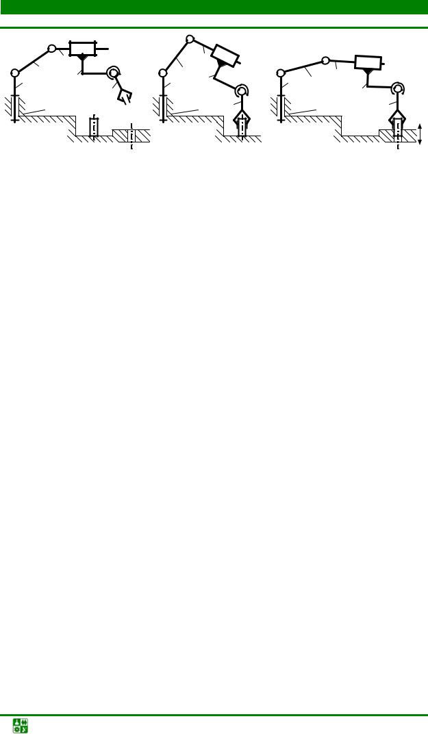
The most common representatives of spatial lever mechanisms are manipulators (Fig. 2.5, a).
A manipulator is a spatial lever mechanism that performs actions similar to those of a human hand.
Manipulators are designed to change the position of objects. The links of manipulators of industrial robots form only the
closed kinematic chains containing kinematic pairs of different classes, which allows such mechanisms to have mobility greater than unity. However, manipulators are characterized by the ability to change the structure of the mechanism during its operation. Depending on the service purpose, two options are possible.
Theory of mechanisms and machines. Textbook allowance |
2. LEVER GEARS
2.2. Structural analysis of lever mechanisms
Rice. 2.5. Diagram of the industrial robot manipulator mechanism
First option: you need to change the position of a stationary object (Fig. 2.5, a). At the initial moment of time, the object whose position needs to be changed lies on a stationary plane and is at rest. Accordingly, the object and the plane impose certain connections on each other. Moreover, if the relationship between the plane and the object does not change its kinematic state, then they can be considered as one fixed link, which is a stand. At the moment of time corresponding to the capture of the object in question by the output link, this link also becomes motionless and must be considered as an element of the rack (Fig. 2.5, b). Accordingly, the number of moving links in the structure of the mechanism decreases by one, and the open kinematic chain that the mechanism had until this moment becomes closed, which leads to a decrease in its mobility. At the next moment in time, there will be a need to tear the object away from the stationary plane in order to move it further. However, to perform such an action, the manipulator, which at a given moment has a closed kinematic chain, must have mobility at least equal to one. As soon as an object is separated from a fixed plane, it will lose its previously existing relationship with this plane, and in the future it must be considered together with the output link as one moving link. At the moment of restoration of mobility by the output link, the kinematic chain of the manipulator again becomes open, which leads to the previous mobility of the mechanism and the ability to move an object according to a given law.
Second option: you need to install the part into a hole of a certain shape made in a fixed surface. At the moment of time corresponding to the installation of the output link of the part into the hole, the output link remains movable, and the kinematic chain of the manipulator closes (Fig. 2.5, c). In this case, the number of moving links is maintained, and the mobility of the mechanism changes in proportion to the mobility of the new kinematic pair formed by the part and the fixed surface into which it is installed. At the moment of termination of the connection between the output link and the part
Theory of mechanisms and machines. Textbook allowance |
2. LEVER GEARS
2.2. Structural analysis of lever mechanisms
the kinematic chain becomes open, and the mechanism restores its properties.
From the situations considered, it follows that ensuring the operability of the manipulator is possible only if the following condition is met:
m ≥ 1.
where m is the maneuverability of the manipulator.
Maneuverability is the mobility of the manipulator with a stationary output link.
The maneuverability of spatial mechanisms is determined by the expression obtained based on the Somov formula:
m =6 n −5 p 5 −4 p 4 −3 p 3 −2 p 2 −p 1
where all coefficients are identical to those presented in § 2.3.
2.3. SYNTHESIS OF LEVER MECHANISMS
The synthesis of mechanisms is carried out in two stages. The first stage is called structural synthesis, and the second is called metric synthesis. The general criteria that are followed at each stage are: minimizing the overall weight characteristics and cost of the mechanism, as well as ensuring the manufacturability of the links and fulfilling the operating conditions. However, each stage has different goals.
Let us characterize each of the stages separately.
Structural synthesis is the process of designing a new or modernizing (improving) an existing structure of a mechanism that has the required properties: a given number of movements, the absence of local movements and redundant connections, a minimum of links, the use of kinematic pairs of a certain type.
At the stage of structural synthesis, a structural diagram of the mechanism is formed, which determines the number of links, the number, type and mobility of kinematic pairs, as well as the number of redundant connections and local mobility. The introduction of the mechanism of each redundant connection and local mobility into the structural diagram must be demonstrably justified. The main conditions when choosing a structural diagram are the specified parameters: the required number of movements, the absence of local movements and redundant connections, minimizing the number of links, the use of kinematic pairs of a certain type or class. At the same time, the determining conditions are: the given law of motion and the location of the axes of the input and output links. If the axes of the input and output links of the mechanism are parallel, then a flat block diagram is selected. When the axes of the input and output links intersect or cross, use
Theory of mechanisms and machines. Textbook allowance |
2. LEVER GEARS
2.3. Synthesis of lever mechanisms
uses a spatial scheme. In most cases, the task of structural synthesis comes down to choosing a structural diagram of a mechanism from a set of standard diagrams.
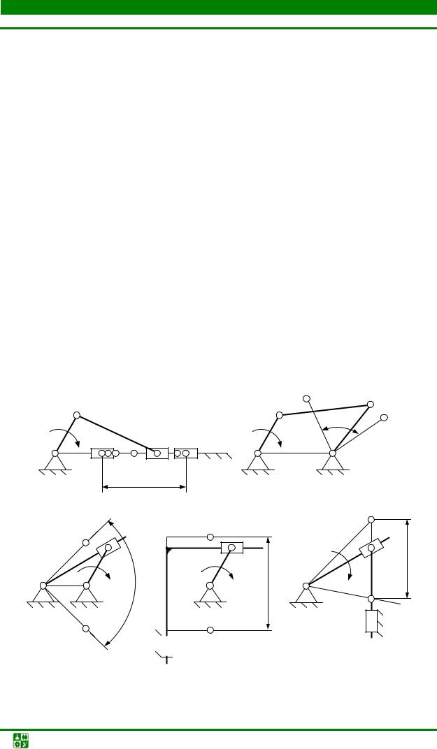
The structural synthesis of flat lever mechanisms is carried out in accordance with the structural classification of L.V. Assur (see Fig. 2.3). As an example, consider the structural synthesis of a crank-slider mechanism (Fig. 2.6).
Rice. 2.6. Scheme of structural synthesis of a crank-slider mechanism
The result of the first task of structural analysis shows that the mobility of the mechanism is equal to unity, therefore, as the primary mechanism we select a group of links of the corresponding mobility, the links of which form a rotational kinematic pair of the fifth class (Fig. 2.6, a). To the selected primary mechanism we attach a structural group of links of the 2nd class of the 2nd order of the 2nd type (Fig. 2.6, b). The mechanism obtained in this way will have a rational structure, that is, its structural diagram will not contain structural defects (Fig. 2.6, c).
More complex structural diagrams can be obtained by sequentially joining the required number of structural groups of the appropriate class, type and order. At the same time, it is necessary to ensure that the structure of the mechanism remains rational when all other specified conditions are met.
The result of the structural synthesis stage is a structural diagram of the mechanism that satisfies the accepted criteria.
Metric synthesis is the process of determining the basic geometric dimensions of the mechanism links and the configurations of the working surface profiles that best satisfy the given conditions and provide the optimal combination of quality indicators.
The objectives of metric synthesis are:
1) synthesis of the kinematic diagram of the mechanism based on the specified positions of the input or output link;
2) synthesis of the kinematic diagram of the mechanism according to specified geometric parameters;
3) synthesis of the kinematic diagram of the mechanism according to a given law of motion of the output link;
Theory of mechanisms and machines. Textbook allowance |
2. LEVER GEARS
2.3. Synthesis of lever mechanisms
4) synthesis of the kinematic diagram of the mechanism according to the given kinematic parameters: average speed of the output link, coefficient of unevenness of the average speed;
5) synthesis of the kinematic diagram of the mechanism based on a given value of the pressure angle or transmission angle.
The solution to the problems of metric synthesis is the kinematic diagram of the mechanism that satisfies the criteria of both stages of synthesis.
Kinematic diagram- this is a graphic representation of the mechanism, made in a certain scale factor using symbols recommended by GOST.
The kinematic diagram contains information about the number of links and the type of movements they perform, the number of mobility and class of kinematic pairs, the number and type of kinematic chains and the dimensions of the links.
When solving problems of metric synthesis of lever mechanisms, they are guided by the following criteria:
1) condition for the rotation of the links - the designed mechanism must provide the possibility for the input or output links to rotate
gates at an angle of more than 360°;
2) design restrictions on the dimensions of the mechanism - the designed mechanism must have overall dimensions that fit within the specified ranges;
3) accuracy of ensuring the specified law of motion or specified positions of the links of the mechanism - the designed mechanism must ensure the fulfillment of the specified law of motion or specified positions of the links with the required accuracy;
4) limitation on the conditions for the transfer of force factors - the current value of the pressure angle of the designed mechanism should not exceed the permissible value;
5) other conditions and requirements taking into account the specifics of the functioning and operation of the mechanism.
TO methods of synthesis of mechanisms include synthesis by methods of analysis
And methods of direct synthesis (analytical, graphical and graphic-analytical).
Metric synthesis of mechanisms using graphic-analytical methods is carried out in a certain scale factor.
Scale factor- this is a relationship of any real-
a given value l, taken in meters, to the length of the segment l, measured in millimeters and depicting this value as part of the kinematic diagram.
The length scale is the ratio of the length of a segment depicting any value in millimeters to the actual value in meters.
The scale is a standardized quantity, the values of which are strictly regulated by the provisions of GOST. From the provisions of the discipline “Engineering Graphics” it is known that the actual scale is
Theory of mechanisms and machines. Textbook allowance |

2. LEVER GEARS
2.3. Synthesis of lever mechanisms
wearing 1×1, and there are series of enlargement scales and reduction scales. The scale factor is the reciprocal of the scale and is not a standardized value. The values of the scale factor are taken arbitrarily depending on the specified conditions and goals for solving the required problems.
μl =OA l OA,
where l OA is the actual length of the crank; OA is an arbitrary segment.
2.4. QUALITY INDICATORS OF LEVER MECHANISMS
The restrictions and conditions of metric synthesis form the values of quality indicators with the help of which the quality of lever mechanisms is assessed.
Qualitative indicators of lever mechanisms are: efficiency η;
mechanism stroke H;
coefficient of unevenness of average speed k; pressure angleϑ; transmission angleμ.
Efficiencyη is a dimensionless quantity, ha-
characterizing the amount of total energy usefully used by the mechanism. As noted in § 1.4, the efficiency of the mechanism is always less than one, since the process of motion transformation is accompanied by losses of mechanical energy caused by the presence of friction in kinematic pairs. The closer the efficiency value is to unity, the lower the losses, therefore, the higher the quality of the lever mechanism.
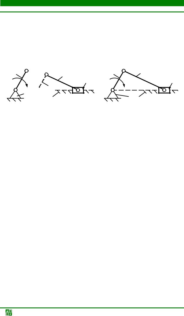
The working area of flat lever mechanisms is usually assessed by the range of movement of the output link, called the stroke of the mechanism.
The stroke of the mechanism is the distance between the initial and final positions of the output link.
For crank-slider (Fig. 2.7, a), sine (Fig. 2.7, d) and tangential (Fig. 2.7, d) mechanisms, the stroke is calculated according to the definition of this parameter, and for hinged (Fig. 2.7, b) and rocker ( Fig. 2.7, c) mechanisms, the value of this parameter can be found by the expression
Н = ψ l,
Theory of mechanisms and machines. Textbook allowance |
2. LEVER GEARS
2.4.
where l ,ψ – length and angle, rad, of the output link span.
Rocker arm swing angle or rocker ψ is the angle between the initial and final positions of the rocker arm or rocker (Fig. 2.7, b, c).
Most flat lever mechanisms have a periodic nature of operation, that is, after a certain period of time, all processes occurring in the mechanism are repeated. In this case, the operating cycle of any mechanism is divided into working and idling phases. During the power stroke phase, the service purpose of the mechanism is carried out, and the idle phase is intended to complete the movement cycle and relieve residual stresses from the working surfaces of the links. The ratio of time spent on working and idling strokes is usually assessed using the average speed unevenness coefficient.
Average speed unevenness coefficient is the coefficient
characterizing the ratio of the idling time T x.x to the working stroke time T r.x :
T x.x | |||||
where θ is the angle between the positions of the connecting rod in the extreme positions of the mechanism.
A, B | A, B | A, B |
||||||||||||||||||||||||||||||||||||||||||||||||||||||||||||||||||||||||||||||||||||||||||||||||||||||||||||||||||||||||||||||||||||||||||||||||||||||||||||||
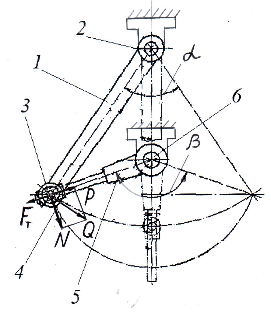
Rice. 2.8. Schemes for determining pressure angles of typical lever mechanisms To assess the quality of transmission of force factors between the links of flat lever mechanisms, the pressure angle ϑ is used. The pressure angle is the acute angle between the active force vector P a, acting from the side of the preceding link, and the velocity vector of the point of its application (Fig. 2.8). The value of the pressure angle forms the conditions for the transfer of forces between the links, determining the magnitude of the driving force of the mechanism Q: Q = P a cos(ϑ ) . From the analysis of the expression it follows that a decrease in the value of the pressure angle leads to an increase in the value of the driving force, and an increase in the pressure angle, accordingly, reduces this force. During the operation of lever mechanisms, the pressure angle is always ϑ ≤ 90°. When the pressure angle ϑ > 90°, jamming or self-braking may occur in the mechanisms. Self-braking, or jamming, is a state of a mechanism that accompanied by values of pressure angles that make it impossible for the links to move at any arbitrarily large value of the driving force. To eliminate such situations, when synthesizing mechanisms, permissible values of pressure angles [ϑ ] are specified, guided by the following recommendations: for mechanisms whose links form only rotational kinematic pairs, the permissible pressure angle lies in the range
2. LEVER GEARS 2.4. Qualitative indicators of lever mechanisms [ϑ ] = 45− 60°, and for mechanisms that have a combination of rotational and translational kinematic pairs, [ϑ ] = 30− 45°. At pressure angle values [ϑ ] = 90°, the mechanism is in the so-called “dead” positions, which in statics leads to jamming of the links; in motion (dynamics), the mechanism overcomes such positions due to the additional volume of kinetic energy. To assess the quality of the hinge mechanism, in addition to the pressure angle, the transmission angle μ is used (Fig. 2.8, b). The transmission angle is the angle that determines the relative position of the axes of the connecting rod and the rocker arm of the hinge mechanism. The values of transmission angles and pressure are interrelated: ϑ+μ =90°. Analysis of the expression shows that an increase in the pressure angle leads to a decrease in the transmission angle and, conversely, an increase in the values of the transmission angle leads to a decrease in the pressure angle. A simultaneous increase or decrease in the values of pressure and transmission angles is impossible. When one of the angles is equal to zero, the value of the second angle reaches a maximum, i.e. 90° ..
|
Leading a link is a link for which the work of external forces applied to it is positive, slave– negative or equal to zero.
In Fig. Figure 13.2 shows a four-joint mechanism. To the input link 1 a driving moment is applied to this mechanism M d , to the output link 3 - moment of resistance M c3. At the design stage, the masses and moments of inertia of the links in Fig. 13.2 are defined, therefore the driving force acting on the driven link is the reaction F 32 directed along the line Sun , the speed of its point of application on the link 3 - V C sent to side 3 perpendicular to the link 3 . Corner 32 between vectors F 32 and V C - pressure angle in the rotational pair WITH . As this angle increases, the tangential component of the force F t 32 , promoting link rotation 3 in the direction 3 , decreases, and normal F n 32 , which does not affect the movement, but only deforms (compresses) the link 3 , increases. That is, with an increase in the pressure angle, the conditions for the transmission of forces in the gearbox worsen. Since in real gearboxes there is always friction, self-braking or jamming is possible at a certain value of the pressure angle in the gearbox.
Self-locking or jamming- this is a state of the mechanism when, as a result of increasing pressure angles in one of the gearboxes, the movement of the mechanism becomes impossible with an arbitrarily large value of the driving force. Often, to characterize the conditions of force transmission, the force increase coefficient is used (without taking into account friction)
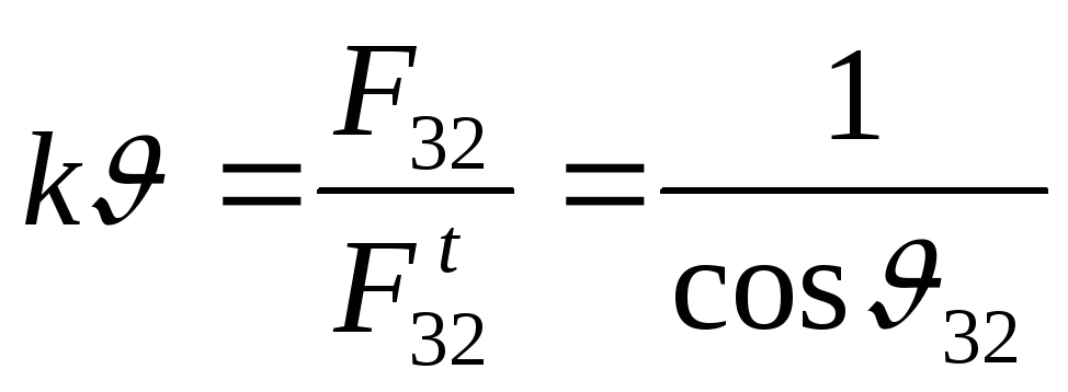
|
|

Since in real mechanisms there is always friction, jamming occurs at pressure angles < 90 . When calculating, the force increase coefficient is specified (for example k = 2 ) and determine the permissible pressure angle [ ] . For preliminary calculations it is accepted for mechanisms only with rotational pairs [ ] = 45 - 60 , in the presence of progressive control points [ ] = 30 - 45 . It should be noted that in the so-called “dead” positions of the mechanism, the pressure angles = 90 . In static conditions, the mechanism may jam in this position; in dynamics, the mechanism moves through these positions using the kinetic energy stored by the moving parts.
The concept of the coefficient of unevenness of average speed
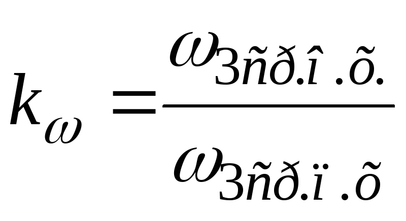
The coefficient of unevenness of the average speed of the output link k is the ratio of the average speeds of the output link during its movement on the return stroke 3wd oh and straight ahead 3wd
|
|
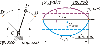
Where 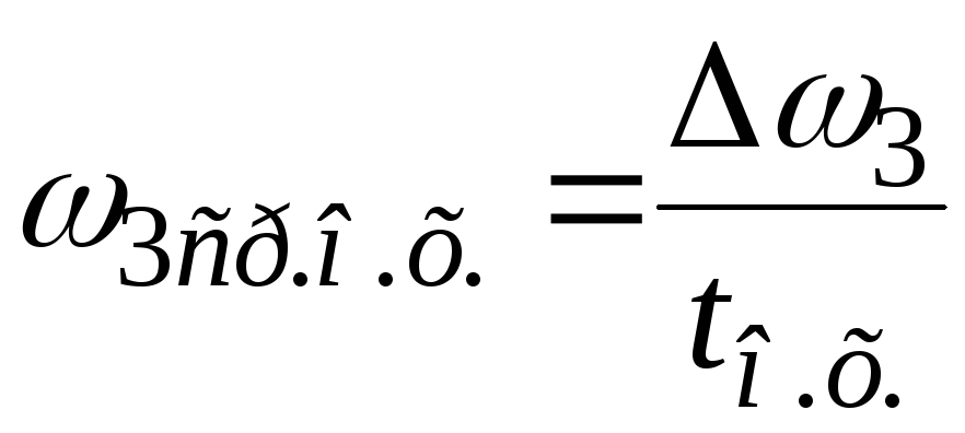

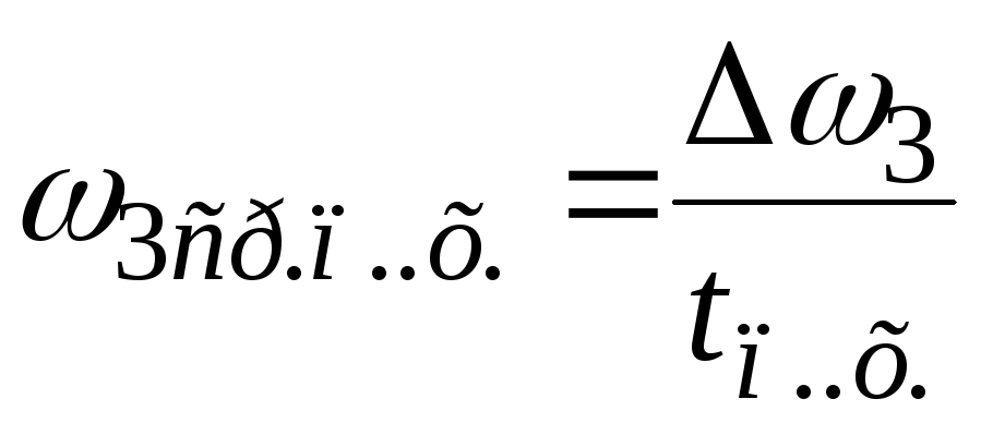
t Oh and t ph - reverse time and forward time, respectively.
When designing technological machines in which the load on the output link of the mechanism in the working or forward stroke is much greater than the load in the idle or reverse stroke, it is desirable that the speed of the output link in the forward stroke is less than in the reverse one. In order to reduce the idle time, it is also necessary to increase the speed during reverse stroke. Therefore, when metrically synthesizing a mechanism, it is often necessary to select link sizes that provide a given coefficient of average speed unevenness.
ALYUSHIN Yu.A.
STRUCTURAL ANALYSIS OF HINGED LEVER MECHANISMS
(Basic concepts and example of doing independent work)
The study of hinged-lever mechanisms involves structural, kinematic and dynamic analyses. Structural analysis includes determining the number of moving links and kinematic pairs (KP), their classification, determining the number of degrees of freedom for a plane and spatial mechanism, eliminating redundant connections (for spatial groups) and “rationalizing” the structure according to Assur with an energy interpretation of possible variants of circuits with redundant mobility. The structure of a mechanism is determined by functionally related sets of elements (links, groups of links or standard mechanisms) and the relationships between them (moving gearboxes or fixed joints). The structure of the mechanism at the level of links, gearboxes and structural groups is displayed on its structural diagram, which differs from the kinematic one with additional information about the type of kinematic pairs connecting these elements.
1. Basic concepts of structural analysis.
1.1. Mobility (number of degrees of freedom) of the mechanism - the number of leading links (independent generalized coordinates) that uniquely determine the position of all other links of the mechanism (on a plane or in space). 1.2. Local mobility – the mobility of individual links of the mechanism, which do not affect the required number of driving links, but allow possible displacements of the links for other purposes, for example, the rotation of a roller pivotally connected to the pusher in the cam mechanism allows the replacement of sliding friction by rolling friction on the surface of the cam.1.3. Connection - restriction imposed on the movement of a body (mechanism link).
1.4. Assur structural groups. Any mechanism can be represented as a combination of one or more two-link (primary) mechanisms and one or more Assur groups. Assur structural groups are kinematic chains formed only by movable links of a mechanism, the mobility of which (on the plane) is zero. Structural formula of the Assur groupFrom here
![]() ,
,
Where  number of links;
  – the number of lower CPs in the structural group. Since all numbers must be integers, the number of links in a structural group must always be even, and the number of lower CPs must be a multiple of 3. 1.4.1. Assur Group
– flat kinematic chains with zero mobility. 1.4.2.
Class
Assur structural group is the number of kinematic pairs included in a closed loop formed internal
kinematic pairs of the group. 1.4.3.
Order
The Assur group determines the number of kinematic pairs with which it is attached to the stand, initial mechanism or other groups. 1.4.4.
Leashes
Assur structural groups are called analogues of the mechanism elements to which this group is attached. They are usually shown as dotted lines extending from free CPs (see Fig. 1). Given this concept order group determines the number leashes, with which it is attached to the stand, initial mechanism or other Assur groups.
– the number of lower CPs in the structural group. Since all numbers must be integers, the number of links in a structural group must always be even, and the number of lower CPs must be a multiple of 3. 1.4.1. Assur Group
– flat kinematic chains with zero mobility. 1.4.2.
Class
Assur structural group is the number of kinematic pairs included in a closed loop formed internal
kinematic pairs of the group. 1.4.3.
Order
The Assur group determines the number of kinematic pairs with which it is attached to the stand, initial mechanism or other groups. 1.4.4.
Leashes
Assur structural groups are called analogues of the mechanism elements to which this group is attached. They are usually shown as dotted lines extending from free CPs (see Fig. 1). Given this concept order group determines the number leashes, with which it is attached to the stand, initial mechanism or other Assur groups. 
Rice. 1. Assur double-lead groups.
Table 1 shows examples of Assur structural groups II-VI classes. Free kinematic pairs are marked with outgoing leads - dotted lines, as in Fig. 1.
Table 1.
| Group | Order |
|||
| II class | ||||
| III class |
|
|||
| IV class | ||||
| V class |
|
| ||
| VI class |
|
| ||


2. An example of performing a structural analysis of a six-link mechanism, the kinematic diagram of which is shown in Fig. 2.
Rice. 2. Kinematic diagram of the mechanism
2.1. Selecting the fixed link– rack “0”, on which the fixed axes of the hinges A and D are fixed, as well as the slider guides. 2.2. We number(Arabic numerals) and classify the moving parts. For the convenience of subsequent dynamic analysis, it is advisable to number the links sequentially from the energy source (leading link) to the most distant consumers. In the mechanism under consideration there are five moving links: link 1 - the crank, makes a rotational movement with a full rotation of 360 0; 2 and 4 – connecting rods, perform plane-parallel movement with rotation relative to the moving axes (the position of the MCS changes over time); link 3 – rocker arm, performs oscillatory motion relative to the fixed axis D; link 5 – slider, performs reciprocating movement along fixed guides. 2.3. We classify kinematic pairs(KP), which determine the relative movement of adjacent links. In some textbooks, kinematic pairs are numbered with Roman numerals, for example, I, II, III, IV, V, VI and VII in Figures 2, 3 and 5. However, with a lower probability of errors, it is more convenient to present the classification of KP in the form of Table 2, in which instead of the Roman numeral The numbers use capital Latin letters with indices that indicate adjacent links connected by corresponding kinematic pairs.Table 2.
| Numbers of adjacent links | Digital KP code | Type of control panel | Designation in Fig. 2, a, 2, b and in the text |
|
| 2&4 (or 3&4) | C 24 (or C 34) |
|||
Where n- number of moving parts ( n = 5), p 1
- number of lower kinematic pairs with the same mobility ( p 1
=7
). There are no higher (with two mobility on the plane) kinematic pairs in the mechanism, p 2
=0
. The total number of degrees of freedom of the mechanism is 1, i.e., for the operation of the mechanism, one driving link is sufficient, which can be used as an AB crank. 2.5. We identify Assur structural groups. To identify the Assur structural groups (with the number of degrees of freedom W = 0), we divide the mechanism into the simplest modules, starting from the one furthest from the leading link. Before this, it is advisable to display pairs combined on kinematic diagrams (see Fig. 2) at one point, in particular, between links 2, 3 and 4, separately, for example, as shown in Fig. 3, a or in Fig. 3, b. These two schemes, generally speaking, correspond to different mechanisms, differing both in the kinematics of links 4 and 5 (if the axes of the hinges connecting links 2, 3 and 4 are not aligned in space), and in the forces transmitted through kinematic pairs between links 2 and 3. If we combine the axes of the rotational kinematic pairs connecting the indicated links, then the kinematic conditions will be unambiguously determined, but the transmitted forces may change due to the appearance of passive forces that do not participate in the transfer of power between connected adjacent links due to the fact that in each moment in time they are directed orthogonally to the speed of movement of these axes (the scalar product of orthogonal vectors is equal to 0!). 

Rice. 3. Possible kinematic schemes of the mechanism.
Kinematic diagrams in Fig. 3 with the image of connecting rod 2 or rocker arm 3 in the form of rigid triangles can lead to an error in classifying the mechanism if it is classified as class 3 (according to the number of sides of the most complex closed contour) and order 3 (according to the number of leads connecting the group with the leading link (initial mechanism) and the stand. To avoid mistakes, it is necessary to divide the mechanism into protozoa modules, the disconnection of which does not disrupt the operation of the remaining part of the mechanism. Therefore, the selection must begin with the two-lead Assur groups of class 1, shown in Fig. 1. The most distant Assur group is formed by connecting rod 4 and slider 5 with three kinematic pairs: C 24, E 45, 5&0 in Fig. 3, a or C 34, E 45, 5&0 in Fig. 3, b, of which two kinematic pairs belong to the “1c” type and one to the “1p” type (5&0). The leads on the gearbox S 24 and 5&0 (Fig. 3, a) or S 34 and 5&0 (Fig. 3, b) connect this Assur structural group (type GDP) with connecting rod 2 (rocker arm 3 in Fig. 3, b) and the strut 0. The number of degrees of freedom (degree of mobility) of the remaining part (links 1, 2 and 3) remains equal W= 1, as in the original mechanism. This confirms that the first structural group has been identified correctly. Next, we separate the second group (links 2 and 3) with three kinematic pairs of type “1v” (B 12, C 23, D 03, Assur structural group of type VBB). The degree of mobility of the remaining part after this - the initial mechanism with the kinematic pair A 01 - remains equal to W = 1. In Fig. Figure 4 shows Assur groups separately. Dotted arrows for each group in Fig. Figure 4 shows the “leads” with which the groups are attached to the rest of the mechanism, containing the drive link 1 (“initial mechanism”), and the rack 0. Moreover, such connection is assumed through the introduction of a kinematic pair belonging to the attached Assur group into the body of the rack or the donor mechanism, from from which it will receive energy to move and perform a technological operation.

![]()
![]()
Rice. 4. Structural groups of Assur. According to Artobolevsky I.I. the class of a group is determined by the number of kinematic pairs that form the most complex closed contour of the group. The order of the group is determined by the number of free elements of kinematic pairs with which the group can be attached to the initial mechanism and rack. Both separable structural groups belong to the 2nd order and 1 class, the whole mechanism belongs to the same class. 2.6. Eliminate redundant connections. Since the assumption of plane-parallel movement of the links relates to an ideal mechanism, and in reality, due to the inaccuracy in the manufacture of elements, primarily the non-orthogonality of the axes of the plane of movement of the links and the non-parallelism of the axes of rotational kinematic pairs, the mechanism is converted into a spatial one, the number of degrees of freedom for a real mechanism should be calculated according to the Malyshev formula. Taking into account the kinematic pairs from Table 2, we obtain: The mechanism has 6 redundant connections, which can be eliminated by replacing the lower kinematic pairs with higher ones. For the more preferable scheme in Fig. 1 from the point of view of energy flows. 3, and one of the options for eliminating redundant connections is shown in Table 3 and Fig. 5.
Table 3.
| Numbers of adjacent links | Type of gearbox for PPD | Type of control panel for spatial movement | Designation in Fig. 2a and 2b |
|
is able to understand the significance of culture as a form of human existence and be guided in his activities by modern principles of tolerance,
Product description
Lever mechanisms. Part 1
Lever mechanisms include mechanisms consisting of links that perform rotational, translational or plane-parallel movement. These mechanisms are distinguished by their simplicity, high efficiency and high load capacity, however, they cannot provide any law of motion of the driven link, which to some extent limits their use in technology.
The following types of lever mechanisms are widely used in technological equipment: four-bar hinge mechanisms, crank mechanisms, rocker mechanisms. Let's look at examples and design features of lever mechanisms.
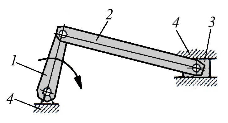
Four-bar articulated mechanisms
The hinged four-bar mechanisms, in turn, are divided into three types: double-crank, in which the driving and driven link can make a full revolution (see Fig. 1a), crank-rocker, in which the driving link, the crank, rotates, and the driven rocker makes a rocking movement (see . Fig. 1b) and two rocker arms, in which both the driving and driven links perform a rocking motion (see Fig. 1c).
An example of a two-crank mechanism is the mechanism for transferring a long piece of angular steel from a rack to a roller conveyor of technological equipment, the design diagram of which is shown in Fig. 2. It consists of two four-ray sprockets 1 and 2, mounted on shafts 3 and hingedly connected to each other by means of axes 5 with four cradle 4, into which the workpiece 6 is placed when transferring, thus forming four two-crank mechanisms. In this case, the shafts 3 on sliding bearings are located in housings 7 and 8, which are mounted on a common frame 10 by means of brackets 9.

Another representative of four-bar articulated mechanisms are double-rocker mechanisms (see Fig. 3), which are used, as a rule, to change (increase, decrease) the swing angle of the driven rocker arm or change the force created on it.
In Fig. 3 A shows a double-rocker mechanism, the design of which (the length ratio and the relative position of rocker arms 1 and 3) allows you to increase the swing angle β α leading rocker arm 1. In Fig. 3 b a double-rocker mechanism is shown, the design of which (length ratio and relative position of rocker arms 1 and 3) makes it possible to reduce the swing angle β driven rocker arm 3 in relation to the swing angle α leading rocker arm 1. If in the mechanism shown in Fig. 3 A, the leading link will be link 3 rotating with a full revolution, and in the mechanism shown in Fig. 3 b, its driving link 1 will make a full revolution, then these double-rocker mechanisms will turn into crank-rocker mechanisms. These mechanisms are rarely used as power actuators of machines and equipment, since they can only operate at a limited swing angle (60 - 90 degrees) due to the increasing amount of losses during the transmission of forces from the driving link to the driven link, with increasing swing angles of the cranks. Such mechanisms are usually used as auxiliary ones, operating at low speeds and loads. This type of mechanism is often used as an actuator in various types of tilters.
 Rice. 4. A tilter for tilting the table of the molding machine.
In Fig. Figure 4 shows the actuator mechanism of the tilter, made according to the articulated four-bar design, consisting of a driving rocker arm 6, rigidly mounted on the drive shaft 3, which is mounted on sliding bearings 2 on the frame 1 and a driven rocker arm 7 pivotally mounted on the frame 1 by means of an axis 5 and a sliding bearing 4 , in this case, the opposite ends of the rods 6 and 7, through axes 8 and 9, are pivotally connected to the connecting rod 10, on which two racks 8 with a transverse crossbeam 11 are rigidly fixed. When the drive shaft 3 rotates (the drive of the tilter actuator is not shown) clockwise, The leading rocker arm 6 also turns in the same direction, and with it the entire mechanism of the four-bar hinge. The choice of swing axes and lengths of rocker arms 6 and 7 is shown in Fig. 4, when rotated, allows the platform 11 to be turned over at an angle, which is in particular used to tilt the table of the molding machine. 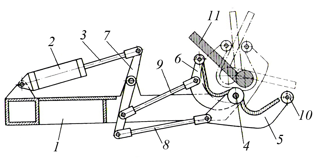
Rice. 5 Design of a welding positioner, the rotary jaws of which are driven rocker arms of articulated four-bars
Figure 5 shows the design of the welding positioner, rotating jaws
which are driven rocker arms of articulated four-links having a common driven rocker arm. It contains, mounted on the frame 1, a drive pneumatic cylinder 2, the rod 3 of which is by means of a double-armed lever 7, the driven arm of which is the leading rocker arm of two articulated four-links containing rods 8 and 9, pivotally connected to the rotary jaws 5 and 6 mounted on a common axis 4, which are driven by the rocker arms of these four-links.
The tilter works as follows. After completing the welding of the first seam of the product 11, a command is given to turn on the pneumatic cylinder 2, the rod 3 of which is retracted and brings the rotating jaws 5 and 6 together, while installing the welded product 11 in a vertical position (at this time, the support rollers 10 roll along the shelf of the product). As a result of this, the center of gravity of the welded product 11 moves to the opposite side of the support prism (not shown in Fig. 5) and with the subsequent opening of the levers 5 and 6, which occurs when the rod 3 of the pneumatic cylinder 2 is extended, the product is placed in a position convenient for welding the second seam.
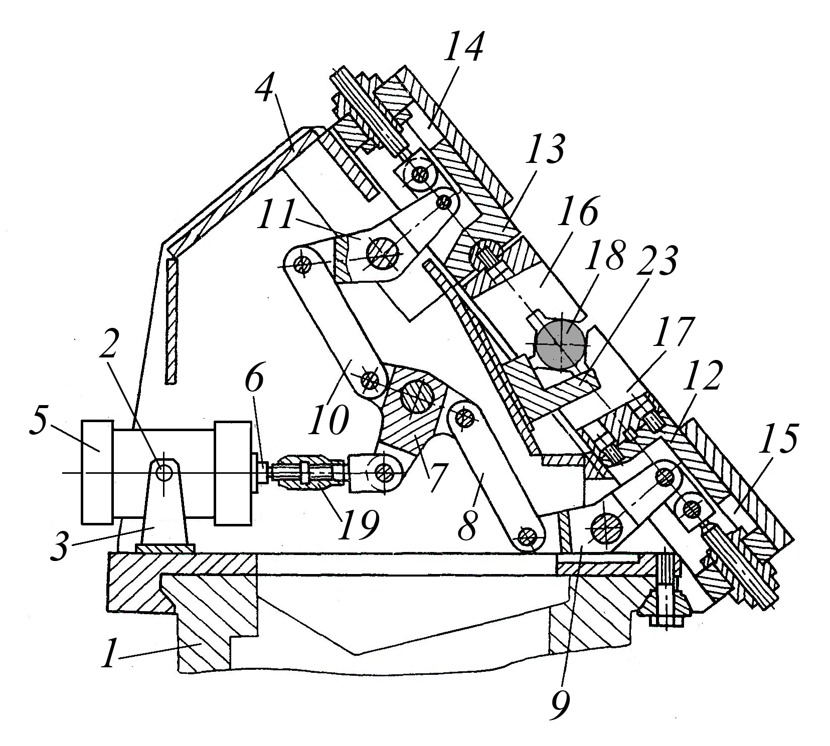
Fig. 6 Design of the clamping mechanism of a milling-central machine containing two articulated four-bars.
Figure 6 shows the design of the clamping mechanism of a milling-central machine, containing two articulated four-bars, the leading link of which is a three-arm lever, while the leading arm of the latter is connected to the rod of the drive pneumatic cylinder, and the driven rocker arms of the four-bars are connected to progressively moving clamping prisms. It contains a housing 4 mounted on the frame 1 of the machine, in which a drive pneumatic cylinder 5 with a rod 6 is hingedly mounted by means of an axis 2 and a bracket 3, the latter using a rod 19 and a three-arm lever 7, intermediate rods 8 and 10 and two-arm levers 9 and 11, is pivotally connected to the sliders 12 and 13, which are installed in the guides 14 and 15 of the housing 4. On the sliders 12 and 13, prisms 16 and 17 are fixed, between which the base cradle 23 is installed.
The clamping mechanism works as follows. To clamp the workpiece (shaft to be trimmed and centered), pre-installed on the base cradle 23, compressed air is supplied to the rod cavity of the pneumatic cylinder 5, while its rod 6 retracts and turns clockwise the three-arm lever 7, which, through intermediate rods 8 and 10, double-armed levers 9 and 11 bring the sliders 12 and 13 together with the prisms 16 and 17 attached to them, which clamp the workpiece 18. To release the processed workpiece, compressed air is supplied to the piston cavity of the pneumatic cylinder 5, while its rod 6 extends through the rod 19 and the lever mechanism returns the sliders 12 and 13 with prisms 16 and 17 to their original position, while releasing the processed workpiece.
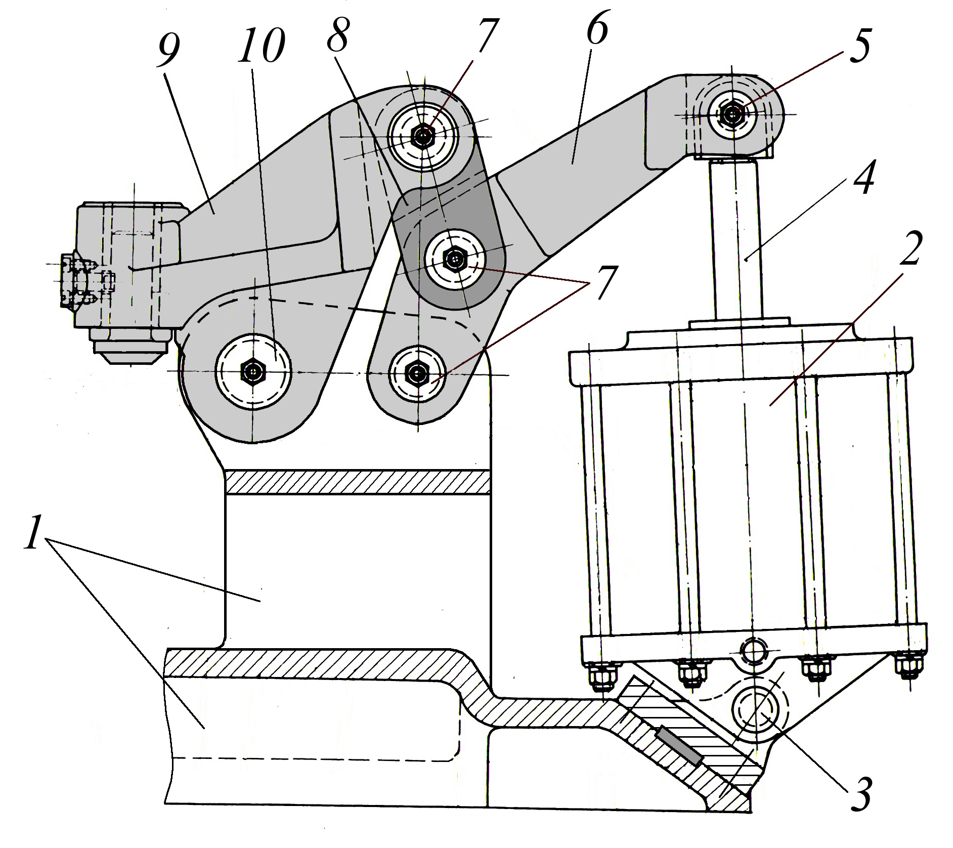
Fig. 7 Design of the actuator of the tabletop press.
Figure 7 shows the design of a tabletop press with a pneumomechanical drive, the actuator of which is a double-rocker mechanism. It contains a power pneumatic cylinder 2 hingedly mounted on the frame 1 via an axis 3, the rod of which 4 is also pivotally connected via an axis 5 to a rocker arm 6, and the latter is pivotally connected to a rod 8 using axles 7, which in turn is connected via an axis 7 to a double-armed lever. 9, mounted using an axis 10 on the frame 1. This design of the actuator driven by a pneumatic cylinder makes it possible to create a small-sized tabletop press capable of developing significant forces.
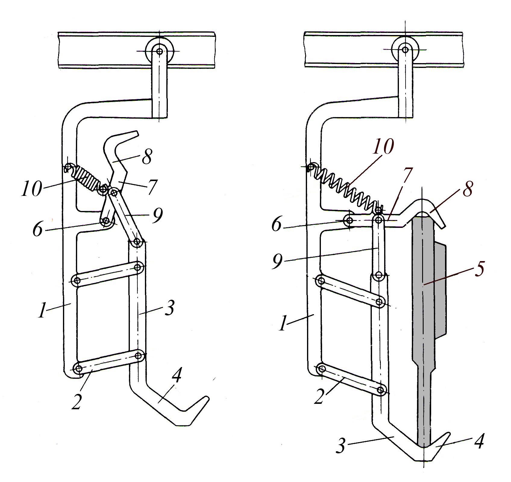
Rice. 8. Design of the conveyor cargo suspension made on the basis
articulated four-bar
In Fig. Figure 8 shows the design of the conveyor cargo suspension, the actuator of which contains a four-bar hinge. This design ensures simple and reliable fixation and clamping of the transported part, as well as its installation and unloading. It contains a fixed stand 1, mounted on the conveyor carriage and connected to it using two equal-length rocker arms 2, a rod 3 with a load-carrying shelf 4, for installing the transported part 5, as well as a lever 7 with a pressure shelf 8, pivotally connected to the fixed stand 1 by means of an axis 6, and by means of a rod 9, it is pivotally connected to the rod 3. In this case, an extension spring 10 is installed between the fixed post 1 and the lever 7.
The suspension works as follows. In the initial position, rod 3 with load-carrying shelf 4 and lever 7 with pressure shelf 8 are in the upper position and do not interfere with the installation of part 5 on the suspension. In this position, part 5 is installed on the load-carrying shelf 4, while under the influence of its weight, lever 7, rod 9 and rod 3, overcoming the force of spring 10, are lowered down. Since the clamping shelf 8 rotates along a larger radius than the point of connection of the rod 3 with the rocker arms 2, then in the same time it will travel a greater distance than the load-carrying fork 4, so the part 5 is pressed by the clamping shelf 8 to the load-carrying shelf 4. For unloading its parts are lifted up by the amount of stroke of the load-carrying shelf 4 and the pressure shelf 8 together with the lever 7 under the action of the spring 10 return to the upper starting position, thus releasing the part.
Crank mechanisms
Of all types of lever mechanisms, crank mechanisms are most widespread in technology due to the simplicity of kinematics, which makes it relatively easy to convert rotational motion into translational motion, which allows their use in actuators of technological equipment, for example, in mechanical presses, and translational motion into rotational motion, which allows them to be used as an actuator of an internal combustion engine. The crank mechanism consists of a crank 1 installed in the frame with the possibility of rotation (crank or eccentric shaft), a connecting rod 2 pivotally connected to it, which is pivotally connected to the slider 3, which, when the crank 1 rotates, performs a reciprocating movement in the guides of the frame 4 ( see Fig. 9).
Rice. 9. Crank mechanism.
In Fig. Figure 10 shows the crank-rod mechanism of a four-cylinder internal combustion engine, consisting of a four-eccentric crankshaft 1 and four piston groups (Fig. 10 conventionally shows one piston group), each of which contains a connecting rod 2 and a piston 3, which is mixed in the liner of the corresponding cylinder.
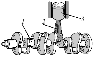
Rice. 10. Crank mechanism
internal combustion engine.
The design of a number of machines and equipment requires the creation of a large slider stroke and a large force at the end of the stroke. In this case, knee-lever mechanisms are used, which also include a crank and connecting rod group (see Fig. 11). Such a mechanism contains a crank 1 mounted on the drive shaft 2, rotating in the bearings of the frame, a drive connecting rod 4, a rocker arm 6, a driven connecting rod 7 and a slider 10 moving in the guides of the frame 11, while the rocker arm 6 is pivotally connected to the frame by means of an axis 8, and the driven connecting rod 7 is connected to the slider 10 via axis 9 (see Fig. 11a). The output link of such a mechanism may not be a progressively moving slider, but a swinging link 10, pivotally connected through axis 9 to the driven connecting rod 7, and through axis 11 to the frame (see Fig. 11b).
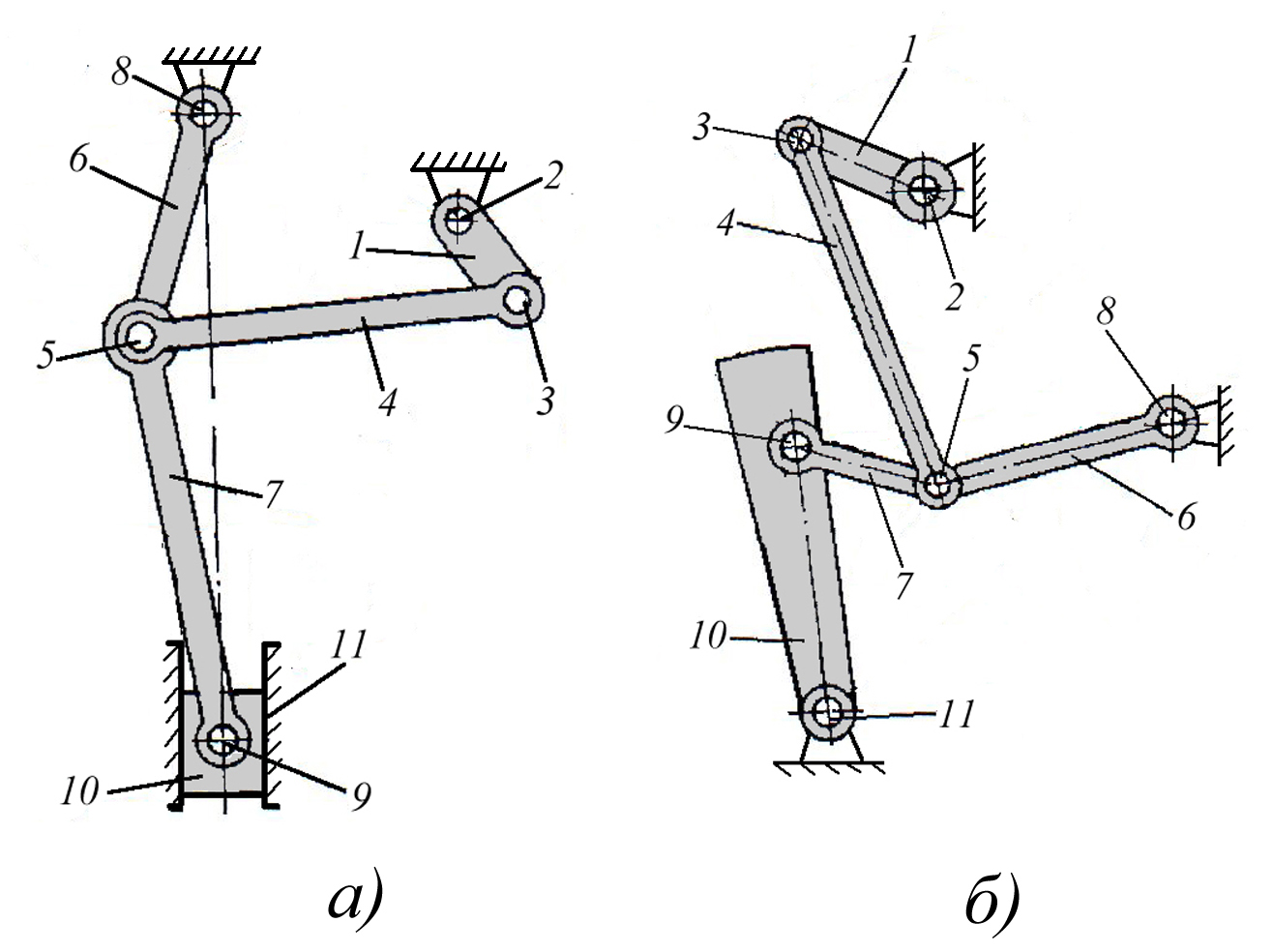
Rice. 11. Crank mechanisms with a large slider stroke and force on the slider at the end of the stroke.
Together with the system of rocker arms, levers and rods, the crank mechanism allows you to obtain different stroke sizes, speeds and the number of strokes of its output link - the slider, which is often necessary in the operation of a number of machines and equipment.
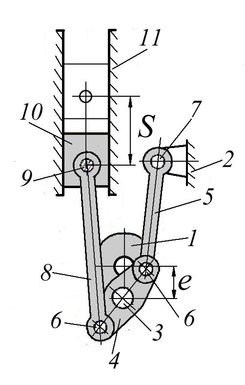
Rice. 12. Design of the crank mechanism with twice the stroke of the slide compared to the eccentricity of the crankshaft.
In Fig. Figure 12 shows a design diagram of a crank-rod mechanism with a double stroke of the slider S compared to the crankshaft eccentricity value e . It contains a crank shaft 1 mounted on bearings in a housing 2, on the crank neck 3 of which there is a rocker arm 4 connected via axles 6 to a rod 5 pivotally mounted in the housing 2 on an axis 7, and a connecting rod 8 pivotally connected via an axis 9 to a slider 10 moving in the guides 11. The presence in the design of the mechanism of a rocker arm 4 hingedly mounted on the crank neck of the crank shaft 1, connected to the rod 5 and the connecting rod 8, imparts to the slider 10 increased movement during its forward and reverse stroke.
![]()
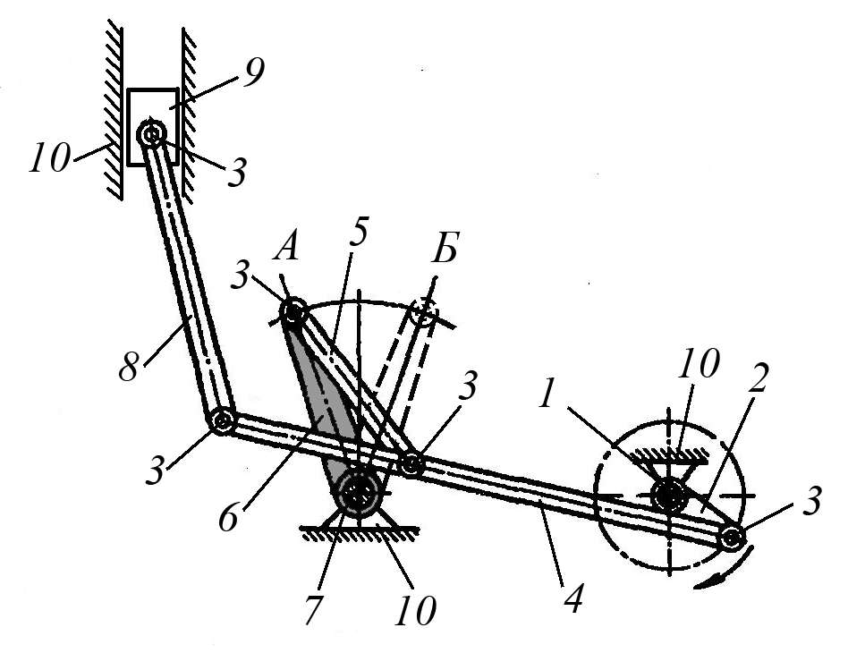
Rice. 13. The design of the mechanism allows doubling the number of strokes of the slider without changing the crankshaft rotation speed.
In Fig. 13 shows the design of a crank mechanism combined with a rocker mechanism, which allows doubling the number of strokes of the slider without increasing the angular speed of rotation of the drive crank shaft. It contains a crank shaft 1, mounted in bearings on the frame and receiving rotation from a drive (the drive is not shown in Fig. 13), a connecting rod 2, a double-arm lever 3, pivotally mounted on the frame by means of an axis 4 and, by means of a connecting rod 5, connected to a slider 6, moving in bed guides 7.
The mechanism works as follows. When turning the crank shaft 1 at an angle of 180 degrees, the double-arm lever 3 rotates at an angle A
, while the slider 6 makes one double stroke, with further rotation of the crank shaft 1 by another 180 degrees, the double-arm lever 3 again makes a turn at an angle A
, returning to its original position, and the slider 6, at the same time, makes a second double stroke in one revolution of the crank shaft.
Rice. 14. The design of the lever mechanism allows you to reverse the movement of the output link.
In some cases, in the presence of a non-reversible drive, it becomes necessary to reverse the movement of the output link of the mechanism; for this, additional links can be built into it, as shown in Fig. 14. This crank-lever mechanism consists of a crank 2 mounted on the drive shaft 1, mounted on bearings in the frame 10, pivotally connected by means of an axis 3 to the driving connecting rod 4, which in turn is pivotally connected by means of axes 3 to the intermediate connecting rod 5 and the driven one connecting rod 6, which in turn are pivotally connected by means of axes 3 to the rocker arm 6 and the slider 9, respectively. To change the direction of the reciprocating movement of the slider 9, the rocker arm 6 is moved from position A to position B and vice versa, after which it is fixed (the latch is not shown in Fig. 14).

Rice. 15. Design diagram of a helicopter swashplate containing a system of articulated and lever mechanisms.
In Fig. Figure 15 shows the original design of a compact automatic swashplate that controls the blades of a helicopter's main rotor, made on the basis of hinged lever mechanisms. It contains a rotating ring 1 with hinged rods 2 that control the main rotor blades, and a spline - hinge 3, which are installed on a non-rotating ring 5 by means of a ball bearing 4. The drive of the spline - hinge 3 is fixed on the shaft 6 of the helicopter rotor drive gearbox. On a non-rotating ring 5, using fingers 7 and 8 and spherical bearings 9 and 10, frame 11 moves. On Frame 11, using fingers 12 and 13 and spherical bearings 14 and 15 at points TO
And M
a lever 16 is fixed, which is mounted in radial plain bearings 19 and 20 and thrust bearings 21 and 22 by means of a pin 17 in a bracket 18 rigidly mounted on the gearbox housing 23. Lever 16 is made of two arms and its driving arm is pivotally connected to the rod 24 for controlling the common pitch of the blades screw The longitudinal and lateral control rods 25 and 26 are pivotally connected to a non-rotating ring 5 on opposite sides relative to the collective pitch control rod 24. The presence of spherical bearings 9, 10, 14, 15 in the design of the machine ensures rotation of the rotating ring 1 along the sphere, which is necessary for the normal operation of the helicopter control system. In this case, the axis passing through the centers of spherical bearings 9 and 10 G
And D
and an axis passing through the centers of spherical bearings 14 and 15 TO
And M
mutually perpendicular, and the location of frame 11 and lever 16, designed to control the overall pitch of the propeller blades and keep the non-rotating ring 5 from displacement and rotation relative to the axis of the drive shaft 6, is arbitrary, relative to the plane of the longitudinal and transverse control of the machine - skew. The axis of rotation of the lever 16 is parallel to the axis passing through the points TO
And M
.
The swashplate machine works as follows. The cyclic pitch of the propeller blades is controlled by tilting the rotating ring 1 with control rods 25 and 26 relative to the two axes of movement of the points A
And IN
. In this case, the rotating ring 1 and the non-rotating ring 5 in the spherical bearings 9 and 10 rotate relative to the frame 11 and the frame together with the rotating ring 1 and the non-rotating ring 5 in the spherical bearings 14 and 15 relative to the lever 16. The overall pitch of the propeller blades is controlled by moving points P
lever 16 by the control rod of the collective pitch 24. Since the lever 16 is hinged on the bracket 18, rigidly mounted on the gearbox housing 23, the non-rotating ring 5 is displaced and rotated radially R
relative to the axis passing through the axis of the bracket 18 and is displaced relative to the axis of the shaft 6 by an insignificant amount. When jointly controlling the general and cyclic pitch of the propeller blades, the points move simultaneously A, B
And P
. In this case, a simultaneous tilt and movement of the fixed ring 5 and the movable ring 1 occurs.
Rocker mechanisms
Rocker mechanisms are mechanisms containing two specific links: a rocker and a rocker stone (see Fig. 16), each of which, performing a rotational or rocking movement, moves progressively relative to each other. The presence of two such links in the mechanism leads to different speeds of movement of the driven link during its forward and reverse motion, which in some cases is an advantage of the mechanism, and in some cases a disadvantage and generally determines the area of its use. There are two main types of rocker mechanisms that differ in the movement the rocker makes; these are mechanisms with rocking and rotational movement of the rocker

Rice. 16. Types of rocker mechanisms
In Fig. 16a shown mechanism with rocking movement of the scenes
consisting of a crank 1, on the axis 2 of which a rocker stone 3 is placed, which has the possibility of translational movement in the groove of the rocker 4, pivotally mounted on a stationary stand by means of an axis 5 and making a rocking motion when the crank 1 rotates. In this case, the rocker 4 makes a forward stroke when the crank is turned 1 per corner A
, and the reverse stroke when turning the crank at an angle IN
, which leads to a difference in forward and reverse speeds due to the inequality of these angles. In Fig. 16b shown mechanism with rotational movement of the scenes
consisting of a crank 1, on the axis 2 of which a rocker stone 3 is placed and a rocker 4, pivotally mounted on a stationary stand by means of an axis 5 and performing a rotational movement when the crank rotates 1. With this design of the rocker mechanism, the difference in the speed of forward and reverse movement of the rocker is also determined by the difference in angles A
And IN
.
Compared to the hinged four-link mechanism used for the same purposes (see Fig. 3), the rocker mechanism makes it easier to ensure the layout of the drive crank and driven rocker by placing them symmetrically relative to the common axis, which is sometimes necessary during design. But, at the same time, the rocker mechanism has increased losses due to additional sliding friction in the rocker pair and therefore is used mainly in lightly loaded auxiliary mechanisms of technological equipment.
Rice. 17. Crank mechanism changing angle
swing of the driven link.
In Fig. 17. shows the design diagram of the rocker mechanism used to increase or decrease the swing angle of the driven link relative to the driving link. It consists of a crank 1 mounted on a shaft 2, transmitting torque to it, connected to it via an axis 3, a rocker stone 4 and a rocker 5 mounted on an axis 6, mounted for rotation on plain bearings. When crank 1 is turned at an angle A Screw 5 rotates at an angle IN , which, for a given ratio of the lengths of crank 1, link 5 and the distance between them, doubles. And, conversely, with the drive linkage 5, crank 1 will rotate at an angle of half as much.
Rice. 18. Crank mechanism for driving a cross-planing machine.
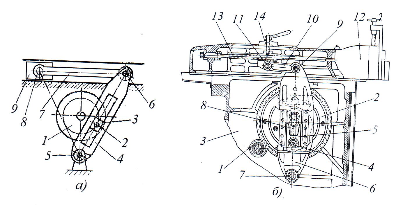
However, in a number of cases, the rocker mechanism can also be used as an actuator of technological equipment. An example of this is the caliper drive of a cross-planing machine, shown in Fig. 18. It consists of a crank 1 mounted on a shaft rotating on bearings in the frame, connected through an axis 2 and a rocker stone 3 with a rocker 4, pivotally mounted in the frame through an axis 5 , and with the help of axis 6 connected to connecting rod 7, which through axis 8 is pivotally connected to slider 9 (see Fig. 18a). In the design of the actuator of the transverse planer (see Fig. 18b), in addition to the links listed in the kinematic diagram, a crank drive is provided in the form of a gear 1 - 2, screw 8, to adjust the eccentricity of the crank axis 4, the value of which determines the stroke of the carriage 12 (slider) , lead screw 13 and clamp 14 fixing its position are necessary to adjust the initial position of the carriage 12 of the machine.

Rice. 19. Crank mechanism of the press.
Replacing the crank-connecting rod actuator of the press with a rocker makes it possible to minimize the gap between the eccentric shaft and the slider, as well as simplify and increase the accuracy of adjusting the size of the inter-stamp space of the press (see Fig. 19). Its design contains a frame 1, in the guides 2 of which there is a slider 3 connected to an eccentric shaft 4 through a rocker stone 5, rollers 7 and a rocker 6 located inside the slider 3 and in contact with it by means of a key 9 and a screw 8. To ensure the connection of the stone 5 and the backstage 6 of the minimum gap required only for the sliding of the stone 5 in the groove of the backstage 6, a wedge mechanism is installed between them, consisting of a wedge 10 and an adjusting screw 11. For precise adjustment of the size of the interstamp space, a screw 8 is provided, the rotation of which leads to the movement of the backstage to the right or left 6 along the inclined groove of the slider 3 in which it is located, as a result of which the slider moves up or down. When the eccentric shaft 4 rotates, the stone 5 makes a flat, parallel movement, the vertical component of which is transferred to the slider 3 due to the ability of the stone 5 to move freely on rollers 7 in the horizontal direction in the groove of the slide 6.

Rice. 20. Mechanism with a rotating slide.
In Fig. Figure 20 shows a mechanism with a rotating slide used in slotting machines to increase the return speed, called the Whitworth mechanism. It contains a gear 1 that meshes with a gear 3 located on an axis 5 and imparts rotation to it at a constant speed, a rocker stone 4 that fits into the groove of a rotating rocker 2, the axis of which 6 passes through the axis 5 and is displaced relative to the axis of rotation of the wheel 3 by the amount of eccentricity e , as well as connecting rod 7 connected to the machine slider. Since the center of rotation of the rocker 2 is offset relative to the axis of rotation of the gear 3, which in this case is the crank, the rocker stone 4 rotates at an angle during the working stroke A , and during the reverse stroke at an angle IN . Because the angle A more angle IN by an amount determined by the magnitude of the eccentricity, then the reverse speed of the slide 2 and the connecting rod 7 associated with it is greater than the speed of the working stroke by an amount proportional to the ratio of these angles.
Rice. 21. Rocker mechanism that transmits stop motion to the driven shaft.
A rocker mechanism can be used to transmit rotation from a drive shaft rotating at a constant speed to a driven shaft that rotates intermittently. The design of such a mechanism is shown in Fig. 21. It contains, installed in the housing 9 and rotating at a constant speed, a drive shaft 4 with an eccentric 7 rigidly fixed to it, on which a two-arm connecting rod 8 is mounted, hingedly connected to the drive slides 2 and the fixing 6, as well as mounted on the shaft 4 with the possibility of free rotation of the driven flange 1 with a sleeve 11 and the link 10 with a sleeve 12. In this case, the flange 1 is made with radial grooves 3, into which, when the eccentric 7 rotates with the connecting rod 8, the drive slide 2 alternately enters, and the fixing slide 6, constantly sliding along the vertical groove 5 in a stationary housing 9, is periodically inserted into the grooves of the driven flange 1. When the drive shaft 4 rotates with the eccentric 7, the double-armed connecting rod 8 periodically inserts and removes from the grooves 3 of the driven flange 1 the drive 2 and the fixing slide 6, which leads to rotation of the driven flange 1 when the drive slide 2 is inserted into the groove 3 and the driven flange 1 stops when the locking slide 6 is inserted into the groove 3. The number of grooves 3 in the driven flange 1 determines the ratio of its rotation speed with the rotation speed of the drive shaft 4. At the beginning of the drive slide 2 entering the groove driven flange 1, the latter begins to rotate slowly, then its speed quickly increases and by the time the slider 2 comes out of engagement it decreases again, which eliminates shocks and impacts even at high speeds of the mechanism.
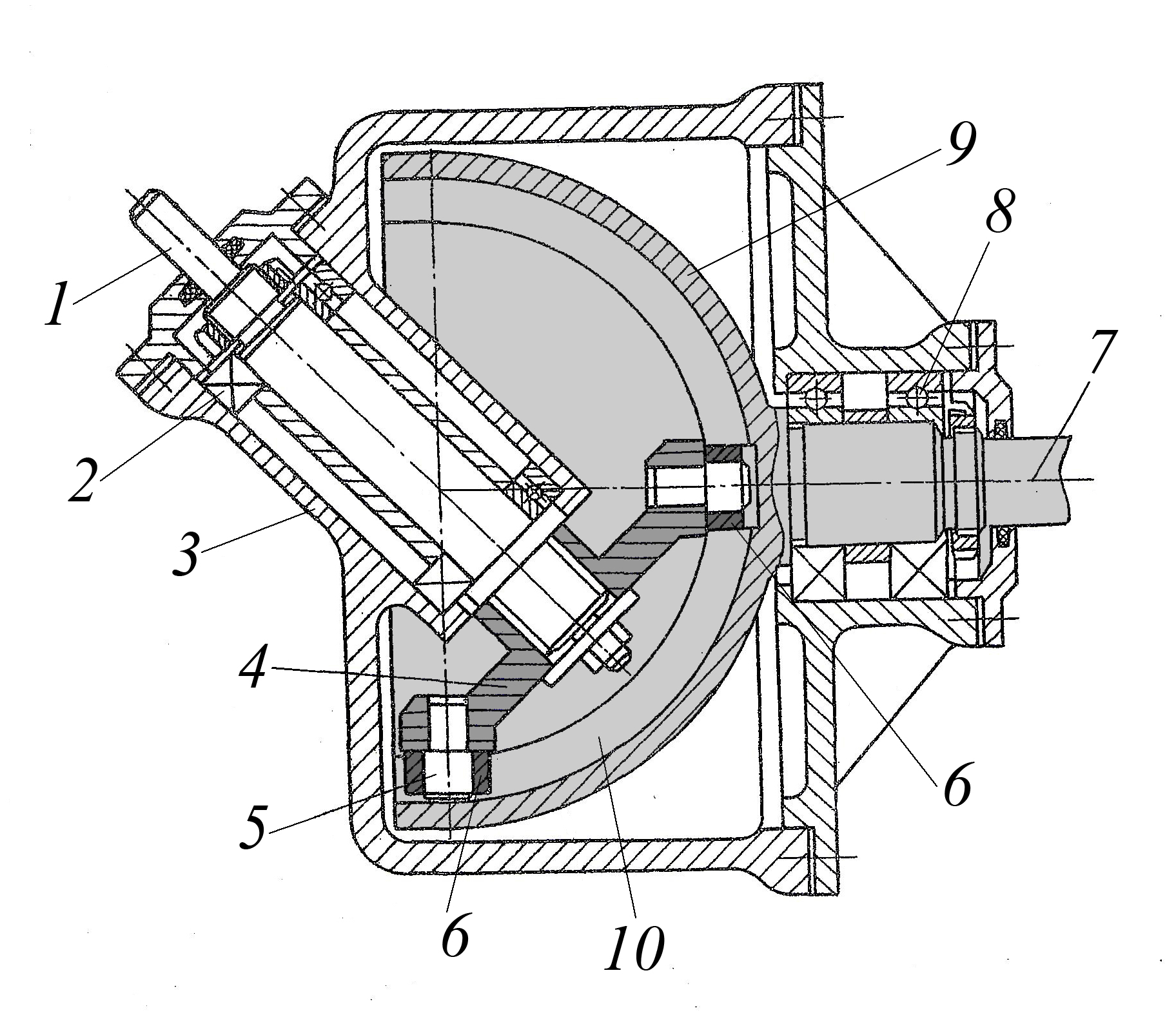
Fig. 22 Design of the rocker mechanism, axis of the drive and driven shafts
which intersect at an angle of 45 degrees
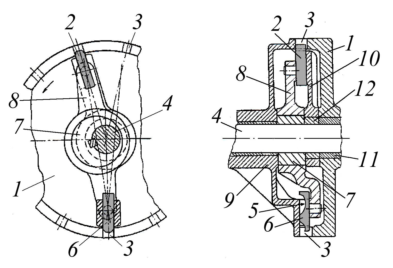
In Fig. Figure 22 shows the design of a rocker mechanism that allows movement to be transmitted between shafts intersecting at an angle of 45 degrees. This mechanism contains a drive shaft 1 installed in a housing 3 by means of bearings 2, at the lower end of which a crank 4, a supporting crank 4, pivotally mounted on axles 5, sliders 6, as well as an output shaft 7 mounted on bearings 8 in housing 3 , which is made in one piece with the slide 9, which has two grooves 10 intersecting at an angle of 90 degrees with which the sliders 6 of the crank 4 are in contact.
The mechanism works as follows. When turning crank 4 at an angle 2𝝅
sliders 6 move along grooves 10, and at the same time rotates the slide at an angle 𝝅
, thus, the gear ratio from crank 4 to the rocker 9 is equal to 2
. The design of the mechanism allows movement to be transmitted from the slide 9 to the crank 4 (in this case, shaft 7 becomes the driving one, and shaft 1 becomes the driven one). In this case, the gear ratio will be equal to 0,5
.
Lever mechanisms with additional
structural elements
When lever mechanisms are used as part of technological equipment and accessories, to ensure efficient operation, additional structural elements are built into it, which allow solving the following tasks:
− adjust the stroke value of the output link (slider, lever, rocker),
− adjust the initial (final) position of the output link,
− protect the mechanism parts from damage,
− communicate complex movement to the output link
− turn the mechanism on and off,
Let us consider examples of the constructive implementation of such lever mechanisms. Regulation of the stroke value of the output link of the lever mechanism is carried out in two ways, by changing the ratio of the lever arms, or by changing the eccentricity value of the drive crank.

Fig. 23 Design of a device that allows you to adjust the length of its leading arm.
Figure 23 shows the design of a device built into the lever of a light-load lever mechanism, which allows you to adjust the length of its leading arm. This lever, consisting of leading 1 and driven 2 arms and mounted on axis 3, has a built-in pin 6, hingedly connected via axis 5 to driving rod 4 and fixed in the required position in groove 10, and an adjusting screw 7 is inserted into its threaded hole. In this case, the driven arm 2 of the lever is hingedly connected through the axis 8 to the driven link of the lever mechanism. When adjusting the length of the leading arm 1 of the lever, the nut 9 is unscrewed, then the pin 6 is moved to one side or the other along the groove of the leading arm 1 of the lever using the adjusting screw 7, and then the pin 6 is subsequently locked with the nut 9.
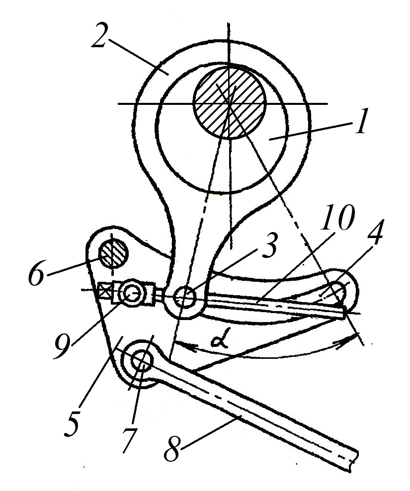
Fig. 24 Design of the crank mechanism with a device for adjusting the stroke of its output link
Figure 24 shows the design of the crank mechanism with a built-in device for adjusting the stroke of its output link, which is made in the form of an intermediate double-arm lever with an adjustable length of the drive arm. It contains a drive crank shaft 1, on the crank of which a connecting rod 2 is installed, pivotally connected via axis 3 with an intermediate double-arm lever 5 mounted on the frame via axis 6, and via axis 7 connected to the driven rod 8. At the same time, on the intermediate lever 5 via axis 9, a lead screw 10 is hingedly mounted, on which a nut is located (the nut in Fig. 34 not shown) is pivotally connected to the axis 3 of the connecting rod 2 and has the ability, like a slider, to move in the radius groove 4 of the intermediate lever 5. When the lead screw 10 rotates, the connecting rod 2 rotates at an angle αi which leads to a change in the size of the leading arm of the intermediate lever 5, and the changing ratio of the lengths of its driven and driving arms makes it possible to change the stroke value of the driven rod 8 of the mechanism. The considered device for adjusting the stroke of the output link of the mechanism differs favorably from that discussed earlier in that it allows, when making adjustments, to maintain the initial position of the output link (rod 8), which is ensured by the presence in the intermediate lever 5 of a radius groove 4, the center of which coincides with the axis of the crank shaft 1 , therefore, when making adjustments, turning the connecting rod 2 does not change the position of the intermediate lever 5.

Rice. 25. Eccentric shaft design, with adjustable eccentricity value.
In Fig. 25 shows the design of an eccentric shaft, in which its eccentricity is adjusted by rotating an eccentric sleeve installed on the corresponding surface of the shaft. The proposed design of the eccentric shaft consists of a shaft 2, on the eccentric neck 1 of which there is an eccentric sleeve 3, with grooves 4 on the inner cylindrical surface into which a key 5 can fit, located in the groove 8 of the eccentric neck 1 and resting on fingers 6 spring-loaded by springs 7 In this case, rings 9 and 10 are installed at the ends of the key 5, on each of which there is a recess 11 inside, limited by a spiral surface 16 with a maximum depth equal to the height of the groove 4. For axial fixation of rings 9 and 10 and the eccentric bushing 3 in the grooves of the eccentric The journals 1 of the shaft 2 are equipped with half rings 12, rigidly fixed in them, and for fixation in the radial direction, spring-loaded ball clamps 13 are mounted in the rings 9 and 10. To rotate the rings, holes 14 are made in them, and for rotation of the eccentric sleeve 3, holes 15 are made in it .
The eccentric sleeve 3 is adjusted as follows. Rings 9 and 10 are rotated through the holes into which the rod or crowbar is inserted until the key 5 is completely removed from the groove 4 of the eccentric sleeve 3. After this, the eccentric sleeve 3 is rotated to the required angle, as a result of which the value of the eccentricity of the shaft 2 changes. Then the rings 9 and 10 are rotated in a similar way until the key 5 enters the corresponding groove 4 of the eccentric bushing and into the recess 11 in the rings, while resting its inclined side surface against the corresponding inclined surface of the recess 11. This is the process of adjusting the position of the eccentric bushing 3 ends.
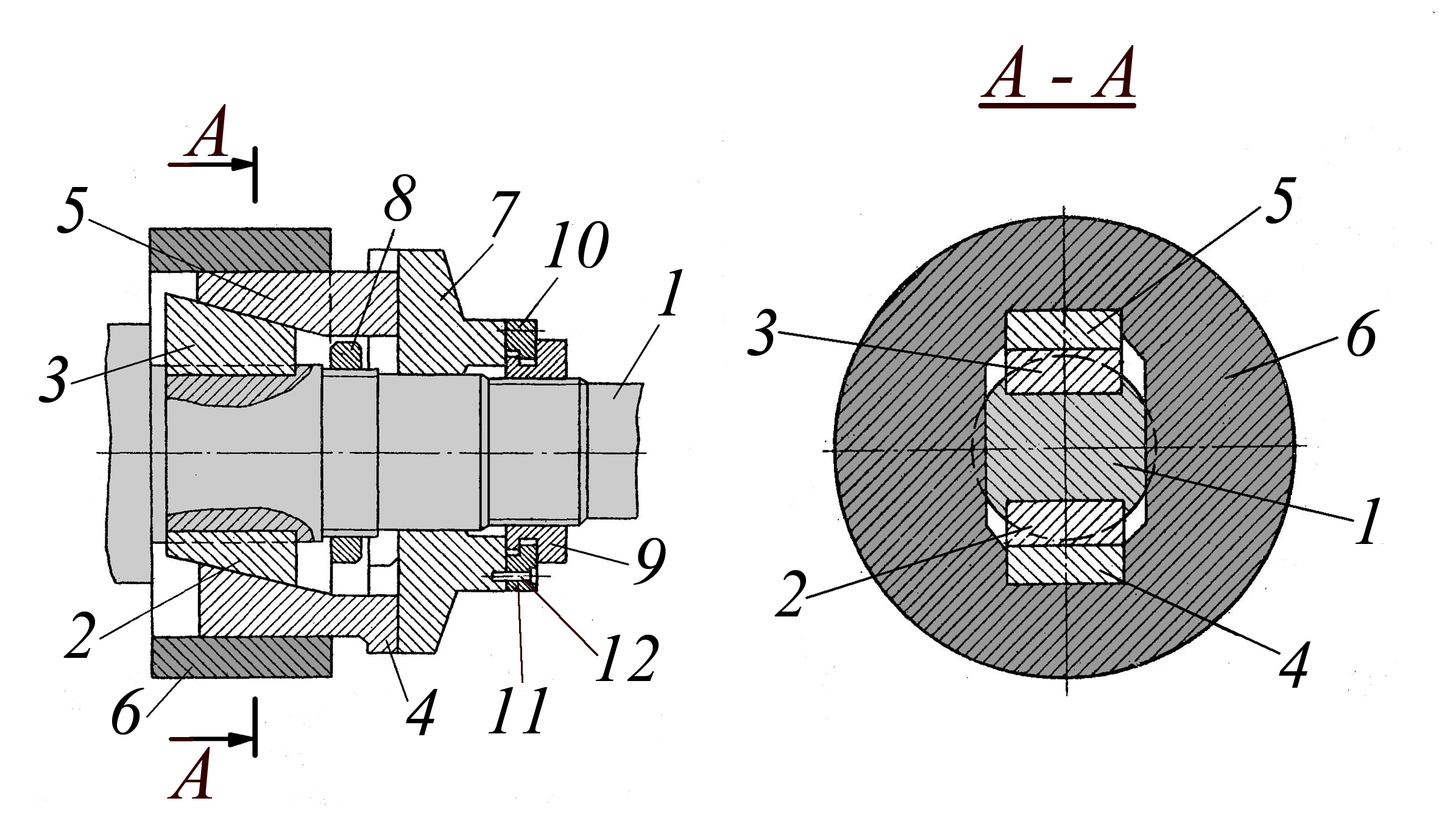
Rice. 26. Design of a wedge device for smooth adjustment of the eccentricity of the eccentric shaft.
In Fig. 26 shows the design of a wedge device for smoothly adjusting the eccentricity of the eccentric shaft. It contains a drive shaft 1 on which wedges 2 and 3 are mounted, which with their wedge surfaces are in contact with the mating surfaces of the wedges 4 and 5, which have the possibility of axial movement in the longitudinal grooves of the eccentric 6 and radial movement in the corresponding grooves of the flange 7, the latter is installed on the shaft 1 with the possibility of axial movement by means of a nut 9 located on the threaded part of the shaft. In this case, the eccentric 6 is fixed on the shaft 1 in the axial direction by means of a nut 8, and the nut 9 is connected to the flange 7 using half rings 10, 11 and screws 12.
The device works as follows. If it is necessary to change the eccentricity of the eccentric shaft 1, by rotating the nut 9, move the flange 7 in the desired direction, while the wedges 4 and 5, sliding along the mating surfaces of the wedges 2 and 3 fixed to the shaft 1, move in the axial direction together with the flange 7 and sliding radially along the surface of the groove made in it. As a result of such movement of the wedges 4 and 5, the eccentric 6 moves in the radial direction, increasing or decreasing the eccentricity of the eccentric shaft.
If the output link of the lever mechanism is a slider, then its initial or final position is adjusted by changing the length of the connecting rod connected to it, and if the output link of the lever mechanism is a lever or rocker arm, then its angular position is adjusted. Let's look at examples of the design of devices for adjusting the position of the output link of a lever mechanism.

Fig. 27 Lever mechanism with initial adjustment
output link position
Figure 27 shows the design of a lever mechanism in which the transmission of motion from the eccentric shaft to the pusher is carried out through an intermediate double-arm lever. It contains an eccentric shaft 1, a connecting rod consisting of a housing 2 mounted on the crank pin of the eccentric shaft and a rod 3, the threaded ends of which are connected to each other by a threaded coupling 4, the position of which is fixed by locknuts 5, as well as a double-arm lever 7, pivotally mounted on the axis 8, on the driven arm of which a roller 10 is installed on the axis 9, which is in constant contact with the pusher 11. This design of the connecting rod allows, by adjusting its length, by screwing or unscrewing the threaded ends of the body 2 and the rod 3 into the coupling 4, to change the position lever 7 and, accordingly, the initial position of the pusher 11, what is necessary when setting up the mechanism as part of the equipment?

Fig. 28 Crank mechanism with a device for changing the length of the connecting rod
Figure 28 shows the design of the crankshaft-connecting rod mechanism of the press, in which the initial position of the slider is adjusted by changing the length of the connecting rod. It contains a connecting rod 1 installed on the crank pin 3 of the crankshaft and connected to the slider 5 of the crank mechanism via an eccentric bushing 2 and an axis 4 located in its hole, while in the eye 7 of the eccentric bushing 3 an axis 8 with a bushing 9 is pivotally mounted in a threaded move away from which the adjusting screw 10 is located. The ball support 12 of the screw 10 is installed in the glass 14 on the thrust bearing 15 and is fixed by the cover 17, while the square shank 16 of the screw is passed through the hole in the cover 17. Connecting rod 1 is in contact with the crankpin 3 of the crankshaft by means of a sliding bearing 18, with the eccentric bushing 2 by means of a sliding bearing 19, and eccentric bushing 2 with axis 4 by means of a sliding bearing 20. In the axial direction, axis 4 is fixed with a washer 21 and bolts 22.
To change the length of the connecting rod 1, the adjusting screw 10 is rotated by the square head 16 in the desired direction, which, when screwed in or unscrewed from the threaded bushing 9, forces the eccentric bushing 2 to rotate around the axis 4, and thereby changes the position of its axis, lengthening or by shortening the connecting rod 1, which leads to a change in the initial position of the slider 5
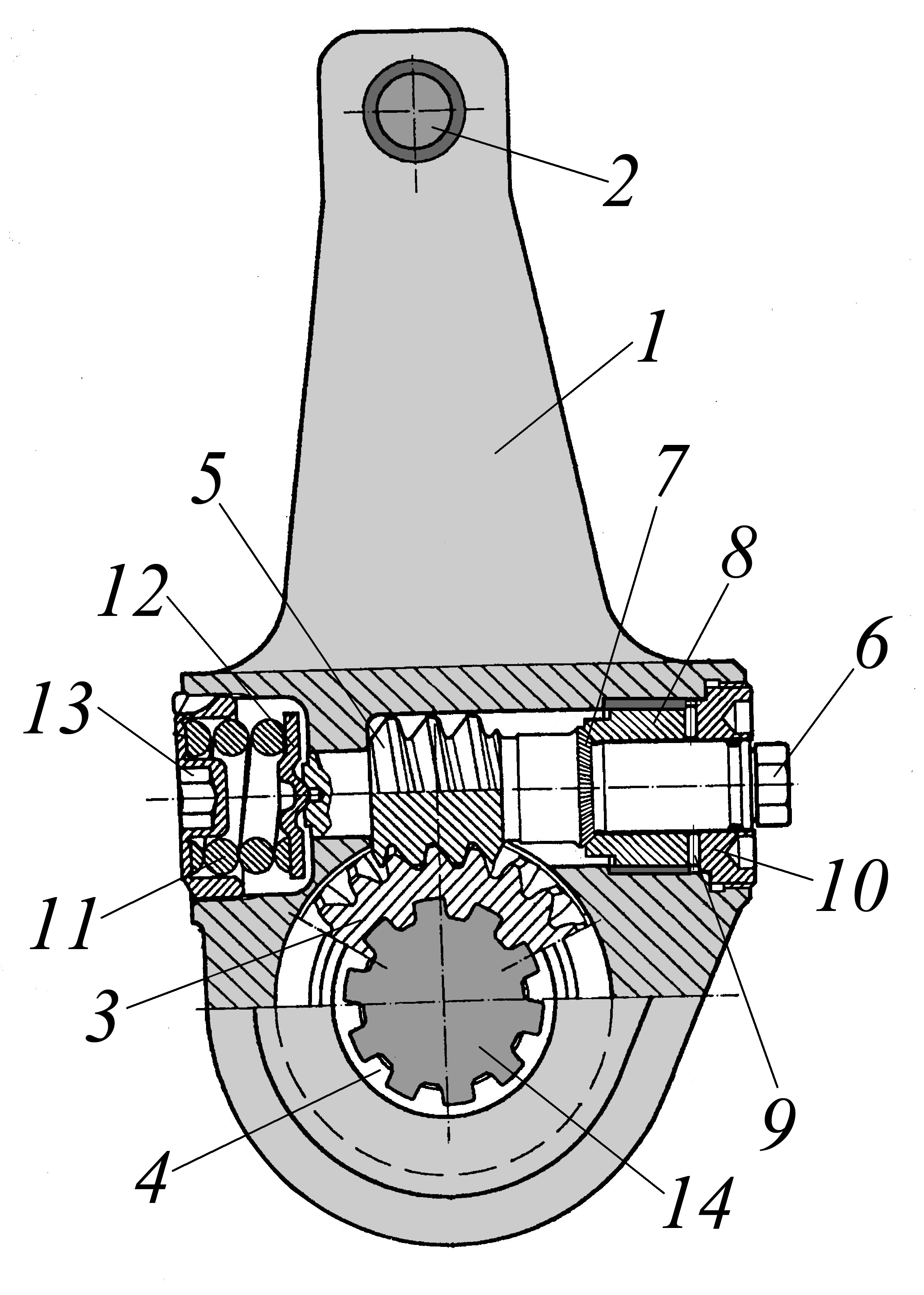
Fig. 29 Rocker with a built-in device for adjusting its angular position
Figure 29 shows the design of a device built into the rocker arm, which allows you to adjust its angular position relative to the axis on which it is installed. This device, built into the rocker arm 1, which is pivotally connected through the axis 2 to the drive rod of the lever mechanism, consists of a worm wheel 3 located in the bore of the rocker arm and with its internal splines 4 contacts the splined surface of the axis 14, and also engages with the worm 5 installed in the boring of the rocker arm, made perpendicular to the axis of the worm wheel. In this case, the left journal of the worm 5 with the hexagonal end 6 placed in the hole in the cover 10, through a set of rollers 9, is in contact with the sleeve 8, on the right end of which there are conical teeth 7, which contact with the mating teeth made on the worm 5, forming an engagement. The left end of the worm 5 with its central conical hole is in contact with the mating surface of the elastic washer 12, which is pressed by the spring 11 and the cover 13.
Adjustment of the angular position of the rocker 1 relative to the axis 14 is carried out as follows. To turn the rocker 1 in one direction or another, the worm 5 is rotated by a hexagonal head 6 with a wrench in the desired direction, while its rotation is transmitted to the worm wheel 3, which, being fixed by means of a splined connection on the shaft 14, remains motionless, and the rocker 1 rotates in the desired direction side, changing its angular position relative to shaft 14.
The sliders of crank and connecting rod mechanisms, which are the actuators of technological equipment, in particular mechanical presses, are subject to strict requirements for their position and movement in relation to the base part of the equipment (for a mechanical press this is the requirement for the perpendicularity of the slider stroke to the base surface of the table), therefore the slider guides have appropriate devices for adjusting their position.

Fig. 30 Design of a device that allows you to adjust the position of the slider
in two planes.
Figure 30 shows the design of a device that allows you to adjust the position of the slider in two planes. This device contains guides 4 of the slide 10, installed on the frame 1 with the possibility of adjustment in two planes, as well as a threaded bushing 3 installed in the threaded hole of the guide 4, in contact with the frame 1 by means of a spherical washer 7 and a pin 14, as well as a shaped washer 9, having a hexagonal head and rectangular protrusions that act as guides in contact with mating grooves in the threaded bushing 3 and nut 12. To adjust the position of the guides in the frontal plane, loosen the screw 8 and by rotating the shaped washer 9, move the bushing 3 in the threaded hole of the axis 2, which leads to a change position of the guide 4. After completing the required amount of adjustment, the screw 8 is tightened. To adjust the position of the guides in the plane perpendicular to the front, the tightening of the nut 12 is loosened and in the same way, by rotating the shaped nut 9, the guide 4 is moved to the required amount, after which the nut 12 is tightened.
In a crank mechanism operating as part of technological equipment, the maximum force occurs when the crank journal of the eccentric shaft is rotated in the region of ± 15 degrees relative to the upper and lower point, as a result of which the resulting torque is not maximum and therefore the known designs of safety devices ( safety clutches built into the mechanism drive) do not protect it from possible overloads. In connection with this, safety devices are built directly into the links of the crank mechanism.
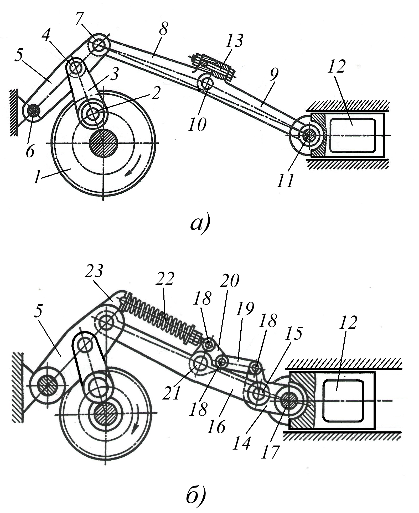
Fig. 31 Design options for safety devices built into the connecting rod of the crank mechanism.
Figure 31 shows two design options for safety devices built into the connecting rod of the crank mechanism. The crank shaft of the mechanism is made in one piece with the gear 1, and its crank pin 2 is pivotally connected to the connecting rod 3, which in turn, through axis 4, is connected to the rocker arm 5 mounted on the frame using axis 6, and through axis 7 is connected to the assembly a connecting rod consisting of a driving part 8 and a driven part 9, connected to each other by an axis 10 with a safety bolt 13 (see Fig. 31a), while the connecting rod is connected to the slider 12 through the axis 11. As the load increases, the safety bolt acting on the slider 12 exceeds the permissible 13 breaks, parts of the connecting rod 8 and 9 rotate relative to each other on axis 10 and the movement from the crank shaft to the slider 12 is not transmitted, which ensures that complex parts of the mechanism are prevented from breaking. After eliminating the reasons for the increase in force acting on the slider 12 and replacing the safety bolt 13, the mechanism can continue to operate.
Figure 31b shows a version of the mechanism with a built-in self-resetting safety mechanism. It contains a one-piece connecting rod 16 hingedly connected by means of axes 15, 17 and an intermediate double-armed lever 14 with a slider 12, and lever 14 by means of axes 18, a rod 19 and a double-armed lever 20, hingedly mounted by means of an axis 21 on the connecting rod 16, through a compression spring 22 connected to the protrusion 23 of the rocker arm 5. As the load increases, the spring 22 acting on the slider 12 exceeds the permissible limit, and the connecting rod 16 and the double-arm lever 14 on the axis 15 rotate relative to each other, thus eliminating the transfer of motion from the crank shaft to the slider. After eliminating the reasons for the increase in force acting on the slider 12, the spring 22 returns to its original position, returning all the parts of the safety device (lever 14, rod 19 and lever 20), as a result of which the mechanism can continue to operate.

Rice. 32. Design of the tilter actuator for transferring the product between conveyors located at different heights.
In Fig. 32 shows the design of a tilter for transferring a product between conveyors located at different levels in height, made according to the design of a four-bar articulated structure, into which non-drive cylindrical and bevel gears are built in, allowing the part to change its position while moving. It is mounted on a rack 1, installed between conveyors 2 and 3 located at different heights. The tilter transfer mechanism is made in the form of a four-link hinge, equipped with a product gripping mechanism with a rotation drive. The transfer mechanism consists of an axis 4 and a shaft 5 mounted on bearings in the bores of the rack 1, with levers 6 and 7 attached to them and a counterweight 8 mounted on the opposite end of the shaft 5, a gear 9 mounted on the shaft 5 and meshed with a rack 10, rigidly connected with a hydraulic cylinder rod 11 mounted on a rack 1. The opposite ends of the levers 6 and 7 are pivotally mounted in the housing 13 by means of a gear shaft 14 and an axis 15, while the gear shaft 14 engages with a gear 22 freely mounted on the shaft 16 of the rotation drive of the gripping mechanism product and connected to it by means of a driver 21 and a flange 20. The product gripper is made in the form of a pin 29, rigidly mounted on the shaft 17 and contains two stops 30 and 31 that limit the rotation of the shaft 17. The rotation drive of the product gripper contains mounted on shafts 16 and 17 and meshed bevel gears 18 and 19 and a spring device consisting of a block 24, movable stops 25 and 26 and springs 27 and 28, which are located in the annular groove 23 of the gear 22.
The device works as follows. In the initial position, the product, which has the shape of a cylindrical glass, is located on the rollers 32 of the upper conveyor 2 and the finger 29 is inserted into its hole. To transfer the product to the lower conveyor 3, the hydraulic cylinder 11 is turned on and its rod rigidly connected to the rack 10 is retracted, while the gear 9 rotates clockwise and rotates the shaft 5 in the same direction, which turns the lever 7, resulting in the transfer mechanism together with the housing 13 and the product located on the finger 29, makes a flat - parallel movement, so the product enters the conveyor 3 in a horizontal position. Simultaneously with the rotation of the levers 6 and 7, the product rotates around the vertical axis at an angle of 180 degrees, which occurs due to the swing of the levers 6 and 7, the rotation of the gear shaft 14, transmitted to the gear 22 and then through the bevel gears 18 and 19 to the shaft 17 , on which pin 29 is fixed. In order for the product, when turning around a vertical axis at the beginning of movement, not to touch the rollers 32 of the upper conveyor 2 and to ensure a guaranteed gap between them, when turning the gear shaft 14, a gear wheel mounted on shaft 16 22, during the initial compression of the spring 27, rotates freely, without transmitting rotation to the shaft 17 with the pin 29 attached to it. When the product is raised above the conveyor 2, the movable stop 25, under the action of the compressed spring 27, transmits force to the driver 21, thereby causing the shaft 16 to rotate and through bevel gears 18 and 19, shaft 17 with pin 29. After installing the product on conveyor 3, its drive is turned on (not shown in Fig. 32) and the product leaves pin 29 and moves in the required direction. The tilter, freed from the product, returns to its original position, and the hydraulic cylinder 11 is turned on; its rod with rack 10 extends and turns gear 9 with shaft 5 counterclockwise, as a result of which levers 6 and 7 with body 13 and pin 29 turn in the same direction . In this case, the shaft 17 with the pin 29 rotates at an angle of 180 degrees in the opposite direction, carried out by the spring 28 and the movable stop 26.

Rice. 33. The design of the crank-connecting rod mechanism allows the slider to mix with the lowered one during a certain period of time.
speed close to constant.
In Fig. Figure 33 shows the design of a crank mechanism combined with a lever-crank system, which allows the slider to move at a reduced speed close to constant over a certain period of time. This mechanism contains a crank shaft 1, the support journals 2 of which are mounted in bearings on the frame, a double-arm lever 3, pivotally mounted on the crank pin of the crank shaft 1 and connected through axes 6 by one arm with a connecting rod 4 and a slider 5, and by the other arm with a rod 7, installed in the slide 8, swinging on the axis 9, while the rod 7 is pivotally connected, due to the axis 12, with the rocker arm 11, mounted on the frame by means of the axis 10. When the slider 5 moves downwards, the rocker-lever system consisting of the rocker arm 11, rod 7, The slide 8 carries out an additional rotation of the two-arm lever 3 around the crank pin of the crank shaft 1 clockwise, which leads to the fact that at a certain point in time the speed of the slider slows down, and its value becomes close to constant. This mode of movement of the slider is necessary when performing a number of technological operations, for example, drawing.
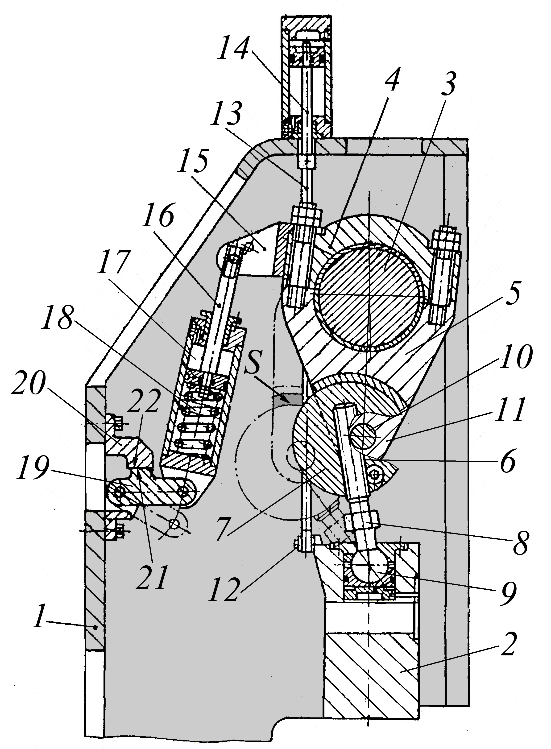
Fig. 34 Design of the crank-connecting rod actuator of the press with a clutchless activation device
Figure 34 shows the design of the crank-connecting rod actuator of the press with a device for clutchless activation, which
made on the basis of a breaking connecting rod. It consists of a slider 2 installed in the guides of the frame 1, which receives a reciprocating motion drive from the crankshaft 3 through an assembled connecting rod 4, connected to the slider 2 using a spherical hinge 9, while the connecting rod 4 contains a driving 5 and a driven 6 elbow, cylindrical surfaces which form a hinge joint, the latter consisting of a disk 7 and an adjusting screw 8, and the disk 7 is made with axles 10, located in the corresponding holes of the eyes 11 of the driving part 5 of the connecting rod 4. In addition, the axles 10 are located eccentrically relative to the axis of the disk 7, which ensures the presence of a gap between the cylindrical surfaces of the driving 5 and driven 6 knees of the breaking connecting rod 4, which is necessary during idling of the actuating crank-connecting rod mechanism of the press. To ensure that it is guaranteed to be in the upper starting position, even when the breaking connecting rod 4 is in the off position, the slider 2 is connected to the balancer rod 14 via an axis 12 and a rod 13. A bracket 15 is rigidly fixed to the driving elbow 5 of the connecting rod, which is pivotally connected to the rod 16 of the control pneumatic cylinder 17 a clutchless activation mechanism, while its body is pivotally connected to a bracket 20, mounted on the rear wall of the press frame 1, by means of a rocker arm 19. The bracket 20 is equipped with a projection 22, and the rocker 19 is equipped with a projection 21, which have the possibility of occasional interaction.
The mechanism works as follows. With constant rotation of the crankshaft 3, on command from the electro-pneumatic automation system, compressed air is supplied to the rod cavity of the control pneumatic cylinder 17, as a result of this and thanks to the articulated connection of the pneumatic cylinder body with the rocker arm 19, mutually opposite movements of its rod 16 and the body occur, which leads to the rotation of the rocker arm 19 against clockwise and its protrusion 21 rests against the protrusion 22 of the bracket 20, and the rod 16 of the pneumatic cylinder, compressing the spring 18, acts on the bracket 15, with which it is pivotally connected, and thereby ensures that the driving 5 and driven 6 of the connecting rod 4 are kept in a closed position (as shown in Figure 34). In this case, movement is transferred from the crankshaft 3 to the slider 2 through a closed connecting rod 4. When the supply of compressed air into the rod cavity of the control pneumatic cylinder 17 is stopped on command from the electro-pneumatic automation system, under the action of the rotating crankshaft 3 and the force of the equalizer 14, the connecting rod elbows 5 and 6 occur 4 and removing their cylindrical surfaces forming the hinge from contact, which leads, due to the eccentric installation of the axles 10 relative to the axis of the disk 7, to the formation of a gap S between them. Then the knees 5 and 6 of the connecting rod 4 begin to make a rocking motion relative to the axles 10 connecting them, and the slider 2, under the influence of the force of the balancer 14, with the crankshaft 3 constantly rotating, is in the uppermost position. At the same time, under the action of spring 18, the body of the control pneumatic cylinder 17 moves and lowers freely and the rocker arm 19 rotates clockwise. After the body of the pneumatic cylinder 17 reaches its lowest position, it begins to make a flat - parallel movement, turning relative to the points of the hinge connection with the bracket 15 and the rocker arm 19, while receiving movement from the crankshaft 3 rotating at a constant speed. With the subsequent supply of compressed air into the rod cavity pneumatic cylinder 17, slider 2 makes a working stroke.
Gear-lever mechanisms.
The combination of lever mechanisms with gears makes it possible to create mechanisms with new properties that are uncharacteristic for both. Most often, such mechanisms are used to obtain the height of the output link, but in some cases they can make it possible to obtain different trajectories of movement of the output link, as well as change the magnitude and speed of its movement
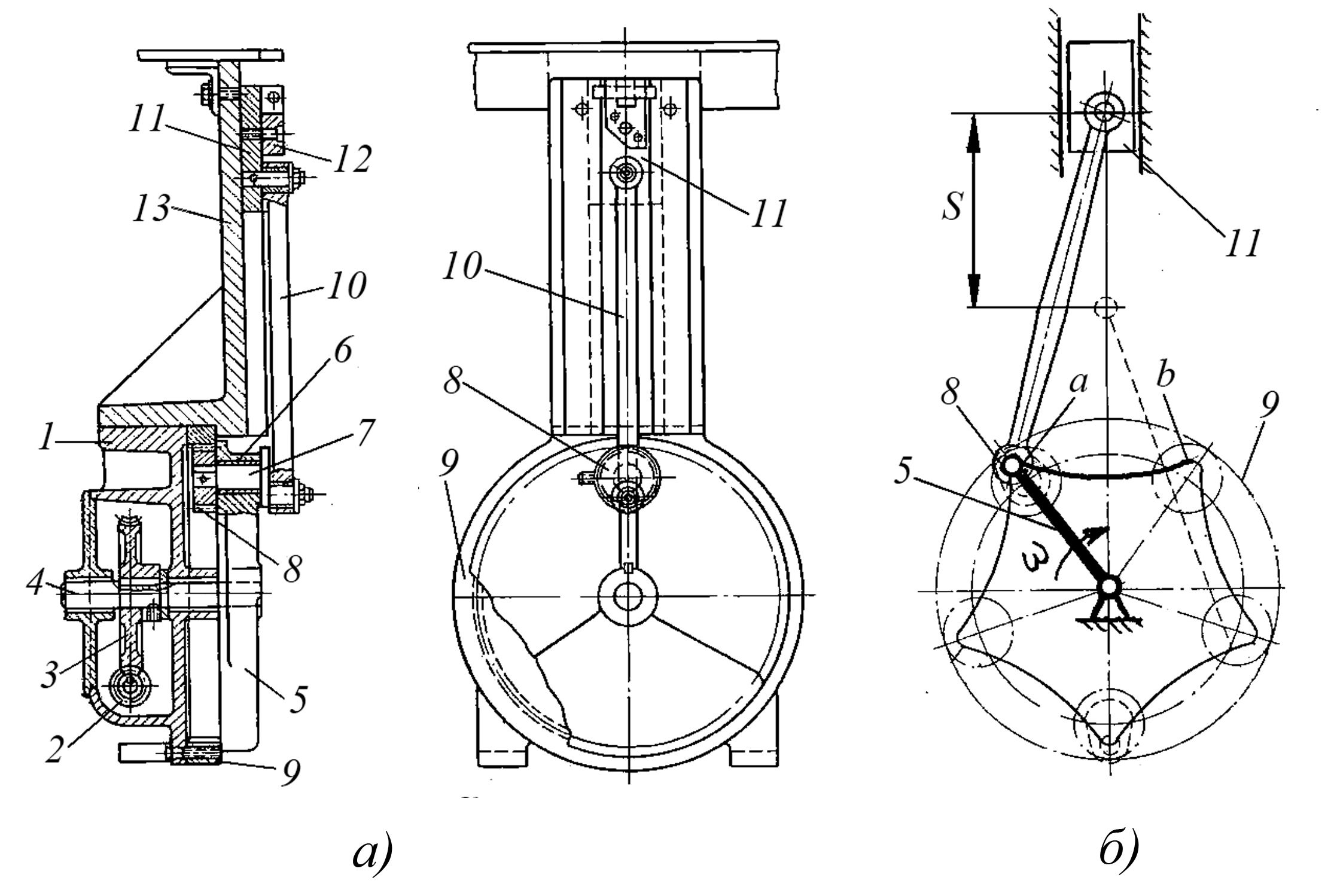
Fig. 35 The design of the gear-lever mechanism, the output link of which - the slider in the extreme forward position makes it stand
Figure 35 shows the design of a gear-lever mechanism, the output link of which, the slider, in the extreme forward position makes a stop at a certain angle of rotation of the drive link - the crank. It consists of a housing 1 in which the worm gear 2, 3 is located, and on its driven shaft 4 a crank 5 is fixed, which is a planetary gear carrier, in the hole of which an eccentric pin 7 is installed on the sliding bearing 6, at one end of which a satellite 8 is rigidly fixed , engaging with the crown wheel 9 mounted in the housing 1, and the other end is pivotally connected to the connecting rod 10, which imparts a reciprocating movement to the slider 11 moving in the guides 12 of the frame 13. In this case, the eccentricity value of the pin 7 is much less than the radius of the main circle of the satellite 8. During a pause in the operation of the device, the eccentric pin 7 moves along an arc whose radius is approximately equal to the distance between the axes of the connection of the connecting rod 10 with the crank 5 and the slider 11, as a result of which it makes a rocking movement without imparting movement to the slider (see Fig. 35b). With such kinematics of the device, the trajectory of movement of the eccentric pin 7 is a closed curve with five protrusions, on which the pause of the slider 11 in the extreme position is expressed by the section a–b on the chart. The pause of the slider 11 occurs due to the fact that the length of the connecting rod 10 is equal to the radius of the arc close in shape to the trajectory section a-b crank 5.
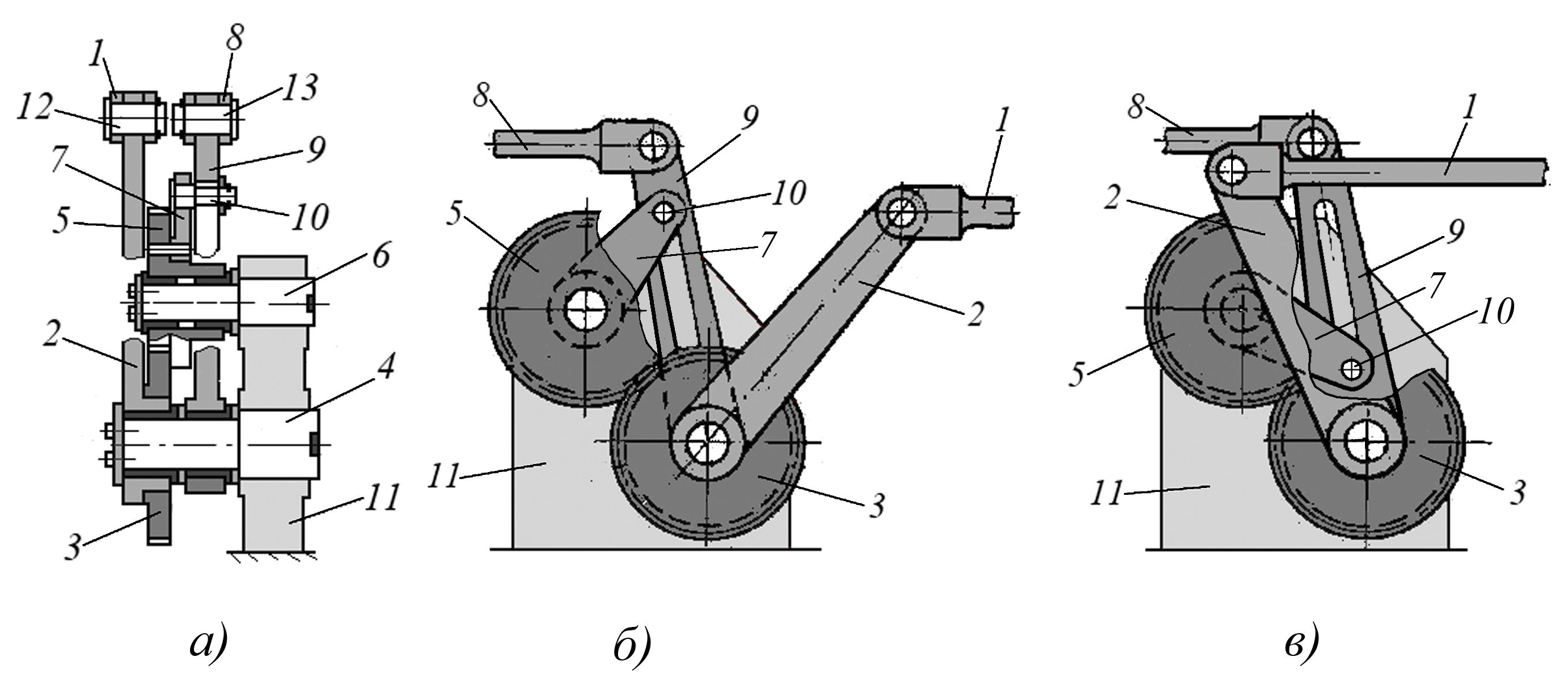
Fig. 36 The design of the gear-lever mechanism makes it possible to obtain twice the number of reciprocating movements of the driven link in relation to the driving one.
Figure 36 shows the design of the gear-lever mechanism, which makes it possible to obtain twice the number of reciprocating movements of the driven link in relation to the driving one. The leading element of this drive is rod 1, which imparts a rocking motion to lever 2, connected to gear 3 and freely rotating with this wheel on axis 4. Gear 3 imparts rotation to wheel 5, connected to lever 7 mounted on axis 6. Pin 10 lever 7, moving in the groove of the slide 9, imparts movement to the rod 8. Axes 4 and 6 are mounted in a stationary housing 11 mounted on the frame. In Fig. 36b,c, rod 1 is shown in the extreme right and left positions, which corresponds to the beginning and middle of its movement cycle. The slide 9 in both cases occupies the same position, since it completes a full cycle and returns to its original position. Lever 2 is moved by rod 1 from the position shown in Fig. 36a to the left, as a result of which gear 3 makes a certain part of the revolution. Gear 5, which is in mesh with wheel 3, makes the same rotation in the opposite direction. Lever 7, connected to wheel 5, rotates with it, and finger 10 moves down along the groove of the link 9. Before finger 10 crosses the center of axis 6, the link turns to the right and reaches its extreme position (see Fig. 36c). With further movement of the rod 1, the finger 10 falls below the center of the axis 6 and moves the slide 9 in the opposite direction, i.e. to the left. At the moment the rod 1 reaches the extreme left position, the slide 9 also takes its extreme left position, making a double move while the rod 1 is only making a forward move. During the time the rod 1 makes the reverse stroke, the link 9 makes another double stroke.
Fig. 37 Design of a gear-lever mechanism that allows you to automatically change the angle of periodic rotation of the driven shaft.
Figure 37 shows the design of a gear-lever mechanism that allows you to automatically change the angle of periodic rotation of the driven shaft. It contains a driven shaft 1, on which a gear 2 and a ratchet wheel 3 are rigidly fixed, as well as a rocker arm 4 mounted on the shaft 1 with the possibility of rotation, while the gear 2 is in constant engagement with the gear 5, which is pivotally mounted by means of an axis 12 on the rocker arm 4 and carries a crank 6, connected via an axis 13 to a rod 7, which in turn is pivotally connected via an axis 10 to the drive rod 8. In addition, a spring-loaded pawl 11 is installed on the rocker arm 4 in contact with the ratchet wheel 3, and an axis 10 is installed in slider 9, which can move along the longitudinal groove of rocker arm 4. In Fig. 37a, slider 9 is shown in its lowest position
The mechanism works as follows. The rod 8, performing a reciprocating motion, imparts a rocking motion to the rocker arm 4. When the rod 8 moves forward, the pawl 11 engages with the ratchet wheel 3, due to which the driven shaft 1, together with the gear wheel 2, makes a rocking motion together with the rocker arm 4. When the rod moves in reverse 8, the pawl 11 slides along the teeth of the ratchet wheel and the driven shaft 1, together with the gear wheel 2, remains stationary. During the reverse movement of the rocker arm 4, the gear 5, rolling along the stationary gear wheel 2 at this time, rotates on the axis 12 and turns the crank 6, which, being hingedly connected to the rod 7, imparts a flat, parallel movement to it, and the latter at the same time moves the slider 9 in the groove of the rocker arm 4 as a result of which the distance from the axis 10 to the shaft 1 increases. Since the gear ratio between gear 2 and gear 5 in this case is chosen equal to two, gear 5 with crank 6 rotates through an angle of 180 degrees, and slider 9 occupies the uppermost position in the groove of rocker 4 (see Fig. 37b). Therefore, during the next forward stroke of the rod 8, the angle of rotation of the rocker arm 4 and, accordingly, the driven shaft 1 will be less due to the increase in the swing radius. When the rod 8 moves in reverse and the rocker arm 4 turns, the gear 5, rolling along the fixed gear 2, will again turn at an angle of 180 degrees, the slider 9 will take its original lower position as shown in Fig. 37a, after which the cycle of operation of the mechanism will repeat.
 Fig. 38 Design of a gear-lever mechanism for linear movement.
Calculations of mechanisms (kinematic, energy, power, strength), as well as their main structural elements (eccentric and crankshafts, connecting rods, sliders, levers, hinge joints) are given in the work
Despite the changes in mechanical engineering over the past 20–25 years, including in the design of technological equipment, primarily related to the type of drive and its control system, lever mechanisms continue to be widely used due to their unique advantages. These advantages lie in the fact that lever mechanisms allow, at high operating speeds, to obtain a given trajectory of movement of the output link of the actuator, as well as in the presence of pulsed technological loads during a certain period of the equipment operation cycle, using in particular the properties of the crank mechanism to minimize the required power. In addition, lever mechanisms make it possible, using simple structural elements, to increase the number of strokes of the output link, change the magnitude of the stroke of the output link, without increasing the movement of the drive, and also solve a number of other problems. At the same time, neither a hydraulic nor a programmable electromechanical drive can compete with lever mechanisms in this regard, which determines a fairly wide range of applications for lever mechanisms.
LITERATURE.
1. Ignatiev N.P. Fundamentals of design Azov 2011.
2. Ignatiev N.P. Design of mechanisms Azov 2015.
The article was written based on information from the relevant sections of the author’s work "Design Fundamentals" published in 2011 and the author's work "Mechanism Design", published in 2015.
In the reference and methodological manual "Mechanism Design" In addition to examples of the design of lever mechanisms, it contains:
– design examples and recommendations for the use of cam mechanisms, intermittent mechanisms and combined mechanisms,
– examples of design and recommendations for the use of the main types of parts of the above mechanisms: crankshafts, connecting rods, sliders, levers and rocker arms, cams and their hinge joints,
– recommendations for choosing the type of mechanism drive and examples of its implementation,
– calculations of mechanisms,
– an example of constructing a cyclogram of the operation of a cam machine,
– methodology for designing mechanisms,
– recommendations for assigning accuracy requirements to mechanisms and their typical parts,
– an example of designing a complex original mechanism
To purchase the full version of the article, add it to your cart,
The cost of the full version of the article is 80 rubles.
Lever mechanisms with lower kinematic pairs have become widespread in modern mechanical engineering. The advantages of such mechanisms include: high manufacturability, the possibility of using rolling bearings in kinematic connections, the ability to transmit large forces with little wear of contacting surfaces, reliability and durability in operation. These mechanisms do not require devices that ensure constant closure of kinematic pairs, unlike cam mechanisms.
Mechanisms are created from the conditions to meet the requirements of the technological process. Mechanism design is a complex task, the solution of which can be divided into two stages. First stage synthesis of mechanisms consists in choosing a kinematic diagram that provides the required type and law of motion of the output link and the general conditions for the operability of the mechanisms. In second stage Structural forms of links and kinematic pairs are being developed to ensure the strength and reliability of the mechanism. Our course only covers First step synthesis.
The mechanism design is usually selected based on experience in relation to given specific conditions. Then determine synthesis parameters, i.e. lengths of links and coordinates of points providing the required trajectories, etc., as well as additional synthesis conditions.
Additional synthesis conditions include condition for the existence of a crank, and force transfer condition.
Force transfer condition
The quality of force transmission in machines is usually characterized by the pressure angle λ, determined without taking into account the gravity forces of the links and inertia forces.
Pressure angle λ is an acute angle between the vector of the force acting on the driven link from the side of the adjacent moving link and the vector of the absolute speed of the point of application of this force.
Motion transmission angle γ complements the pressure angle up to 90°:
γ = 90° – λ .
At the stage of metric synthesis, the maximum permissible angles of pressure [λ max ] and transmission of motion [γ min ] are limited, as a rule, taking them:
[λ max ] ≤ 30° and [γ min ] ≥ 60° for a sliding driven link, and
[λ max ] ≤ 40°...45° and [γ min ] ≥ 50°...45° – for a rotating driven link.
Let us consider the condition for the transmission of forces in a four-bar articulated linkage, which is in equilibrium under the influence of the moments of the driving force. M D and moment of resistance M C (Fig. 3.1). The pressure angle λ characterizes the relationship between the useful resistance force F 23 cos λ overcoming the moment of resistance M With, and force F 23, equal
F 23 = M WITH /( l Sun∙ cos λ).
Fig.3.1. Pressure angle λ in a four-bar articulated link
As the pressure angle increases, more force must be applied F 23 to overcome the same moment of resistance. This leads to an increase in reactions in kinematic pairs and a decrease in the efficiency of the mechanism.
As the mechanism moves, the pressure angle changes. This angle in a four-bar hinge reaches extreme values in positions where the crank OA located on the same straight line with the stand OS(Fig. 3.2).
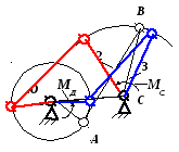
Fig.3.2. The positions of the mechanism at which the pressure angles reach
extreme values
In a crank-slider mechanism, the pressure angle takes on extreme values in the positions shown in Fig. 3.3 when crank OA perpendicular to the trajectory of the slider IN.

Rice. 3.3. The positions of the mechanism at which the pressure angles
have extreme values.
Below we consider the most common problems of kinematic synthesis of mechanisms in course projects.
Synthesis of a four-bar articulated linkage based on the coefficient of change in average speed and two extreme positions of the rocker arm
Coefficient k change in the average speed of the driven link is equal to k = V C 2 – 1 / V C 1 – 2 ,
Where V C 1 – 2 − average linear speed of a point WITH(Fig. 3.4) during the working stroke, V C 2 – 1 − the same for the reverse stroke.
Let's accept k> 1, since when designing mechanisms, as a rule, the time to return to the initial position is taken to be less than the working stroke time, therefore k > 1.
It is not difficult to prove that k= (180° + θ) /(180° – θ).
Where does θ = 180° ( k −1) /(k +1),
where q − angle between connecting rod positions B.C. at the beginning and end of the working stroke.
Let us introduce the following notation:
l 1 – crank length AB,(see Fig. 3.4); l 2 – connecting rod length Sun;
l 3 – rocker length CD; l 4 – distance between supports (stand length AD).

Rice. 3.4. Diagram of the mechanism in positions corresponding to the values of the specified angles ψ
Given the angles ψ 1 and ψ 2, as well as the coefficient k, let us depict the two extreme positions of the rocker arm CD(Fig. 3.5).
Points WITH 1 and WITH Let's connect 2 with a straight line. Let's calculate the angle q between the extreme positions of the connecting rod Sun. At the point WITH 2 construct the angle γ = 90° −
θ, and from the point WITH 1 lower the perpendicular to the line WITH 1 WITH 2 until it intersects with a line drawn from the point WITH 2 and forming the angle γ. Let us denote the point of intersection of these lines ABOUT. Obviously, in a right triangle OWITH 1 WITH 2 corner WITH 1 OS 2 = θ. By three points O, WITH 1 and WITH 2 we describe a circle. Inscribed angle with vertex at point ABOUT rests on an arc  and is equal to the angle θ, as well as all inscribed angles based on the same arc. Let us choose on a circle with center at the point ABOUT arbitrary point A and connect it with straight segments with points WITH 1 and WITH 2. As a result, placing the crank support at the point A, we obtain a diagram of a four-bar mechanism in extreme positions (see Fig. 3.5).

Rice. 3.5. Synthesis of a four-bar hinge according to the coefficient k
changes in average speed and two extreme positions of the rocker
From the figure it follows AC 1 = IN 1 WITH 1 −AB 1 = l 2 − l 1 ; AC 2 = IN 2 WITH 2 −AB 2 = l 2 + l 1 .
Where l 1 = 0,5 (AC 2 −AC 1) μ l / 2; l 2 = AC 2 − l 1 .
Stand length AD = l 4 will be determined by the position of the point A.
Since the position of the point A was chosen arbitrarily, there is a multivariate solution to the problem. This allows you to introduce additional conditions, for example, the condition of force transfer, the presence or absence of eccentricity of the location of the supports relative to the coordinate axis.
Synthesis of the rocker mechanism according to coefficientk changes
average speed of the scenes
Given: coefficient k changes in speed and two extreme positions of the point IN backstage Sun.
Let's consider the rocker mechanism in two extreme positions (Fig. 3.6).

Rice. 3.6. Synthesis of the rocker mechanism
Angle between crank position OA 2 and continuation of the crank in position OA 1 is equal to θ = 180° ( k −1) /(k+1). Angles IN 1 C B 2 and q will be equal to each other, like angles with mutually perpendicular sides.
On a straight line IN 1 IN 2 construct an isosceles triangle with an angle at the vertex WITH, equal to the angle q. On a straight line dividing angle q in half at an arbitrary point, select a point ABOUT, around which the crank rotates OA. Dropping from the point ABOUT perpendicular to line IN 1 WITH(or IN 2 WITH), find the length of the crank OA. The resulting rocker mechanism will satisfy the specified conditions. The construction of the rocker mechanism according to the given conditions occurs as follows. Points IN 1 and IN 2, the position of which is given, we connect with a straight line.
Synthesis of a crank-slider mechanism
Let us accept the following conventions (Fig. 3.7):
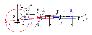
Rice. 3.7. Diagram of the crank-slider mechanism
r– crank length OA;N– stroke of the slider; l– connecting rod length AB;
e– disaxial, i.e. point trajectory offset IN slider relative to the axis Oh ;
L = l/ r– relative length of the connecting rod;
ν = e/r– relative disaxial;
h = H/ r– relative stroke of the slider ;
λ max – maximum pressure angle (see Fig. 3.3);
k − coefficient of change in the average speed of the slider (see § 3.1)
ψ 1 and ψ 2 – acute angles formed by the crank OA with direction Oh in the extreme positions of the slider: φ 1 =  IN 1
Oh, φ 2 = IN 2
Oh
;
IN 1
Oh, φ 2 = IN 2
Oh
;
θ = ψ 2 – ψ 1 – acute angle between the connecting rods in the extreme positions of the slide.
Task 1. Given: Not, L = l/ r.
Find: r; l; ׀λ max ׀.
Crank length OA: r = H / h. Connecting rod length AB: l = L r.
The largest value of the pressure angle ׀ λ max ׀ = arc sin [(1 + ν) / L] .
Task 2. Given: N,k, L= l/ r.
Find: r; l; e; ׀ λ max ׀.
Acute angle between the connecting rods in the extreme positions of the slider
θ = 180 0 ∙( k–1)/(k+1).
We find the relative stroke of the slider from the expression
h = {2∙} 0,5 .
We find the relative disaxial from the expression
ν = [( h –2)∙(L 2 –1)] 0,5 .
Crank length r = H/ h; connecting rod length l = L r; disaxial e =ν r.
The largest value of the pressure angle λ max = arc sin [(1 + ν) / L].